
Installation Sheet

2of2
2018 QuoizelInc.
ReleasedDate:2018-09-13
visit us on-line at www.quoizel.com
(Step 4 Continued)
mounting balls. Note: The Ceiling Canopy (B) should be snug
against the ceiling and the mounting balls. If not, adjust the length
of the nipple on the Crossbar Assembly (A) by unscrewing the
preassembled hex nut and lock washer and then screwing the
mounting screws in or out of the crossbar until the correct length is
achieved. Once the Ceiling Canopy (B) is secure, remove the
mounting ball and Ceiling Canopy (B).
Figure 6
STEP 5 - Wire Connections
A. Wrap bare or green ground wire around green ground screw on the
crossbar, no less than 2 inches from the end of the wire. Tighten the
green ground screw.
B. Use standard wire connectors (not included) to make all wire
connections. Twist connectors until wires are tightly joined together.
Wrap each connection with approved electrical tape and carefully
stuff all the connected wires into the Outlet Box.
Green Ground Screw
on the Crossbar
White wire
from outlet box
White wire
from fixture
Black wire from
outlet box (or Red)
Black wire
from fixture
Bare, or Green
Ground wire
from outlet box
Ground wire
from Fixture
Figure 5
STEP 6 - Install Fixture to Ceiling
A. Carefully tuck all wires into the outlet box and position the Ceiling
Canopy (B) over the outlet box. Align the holes in the ceiling canopy
with the mounting screws, then attach the Ceiling Canopy (B) using
the previously removed mounting balls. Hand tighten until snug.
Mounting Screw
Hex Nut and
Lock Washer
A
Mounting Ball
Ceiling Canopy
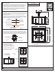
STEP 7 - Install Bulbs
A. Insert bulbs onto sockets and
screw snugly into place.
Your fixture is now assembled
and ready to use. Enjoy!
B. If necessary, adjust the socket
assembly to make sure socket
assembly are parallel with cage.
T8 Vintage Bulb
(recommended
but not included)
Socket
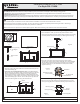
CDL1714EK
FINISH: EARTH BLACK
NOTE: ALL DIMENSIONS ARE ROUNDED UP
TO THE NEAREST 1/4"
5” SQ.
12.25”
6.5”
11.25”
14”
14”
Incorrect
Cage/ Socket Assembly
Orientation
Correct
Cage/ Socket Assembly
Orientation
Socket
Assembly
Cage
Figure 7
Socket
Assembly
Cage