
Installation Guide
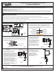

Package Contents
Warnings and Cautions
1of2
Assembly Instruction Sheet #IS-ADA8702LN
For Styles ADA8702LN
Thank you for purchasing a Quoizel product.
Need assistance with parts or assembly? Call Quoizel customer service at 1-631-273-2700
or visit us on-line at www.quoizel.com
2015 QuoizelInc.
Turn off electricity at circuit breaker or main fuse box before installation. Consult a licensed electrician if in doubt.
These instructions are provided for your safety. It is very important you read them completely before installing the fixture. We strongly
recommend that a licensed, professional electrician perform the installation.
Disconnect fixture from power source before replacing bulbs. Make sure bulbs are given sufficient time to cool before removal. Do not subject
glass parts to any shock while in operation or shattering may result.
A
Crossbar
Assembly
x1
Pleasegoto forproduct cleaningtips. Goto the selection.
(2)B10 Candelabra Basebulb 60WMaximum.
20-30minutes
Identifyand inspectall partsbefore beginninginstallation. Checkpackage contentlist anddiagrams belowto besure allparts are
present.If anyparts aremissing ordamaged, donot attemptto assemble,install, oroperate thefixture. Contactcustomer servicefor replacement
parts.
www.quoizel.com Care+ Maintenance
LightSource:
EstimatedAssemblyTime:
Preparation:
ToolsRequired: Flatheadscrewdriver, Phillipsscrewdriver, pliers,wire cutters,wire strippers,electrical tape,safety glasses.
C
Fixture
Body
x1
STEP 3 - Wire Connections
A. Use standard wire connectors (not included) to make all wire
connections. (Connectors are not included with fixture.) Twist
connectors until wires are tightly joined together. Wrap each
connection with approved electrical tape and carefully stuff all the
connected wires into the Outlet Box.
White wire
from supply
White wire
from fixture
Black wire from
supply (or Red)
Black wire
from fixture
Ground wire
from supply
Ground wire
from fixture
Figure 3
May2015
STEP 1 Install Crossbar Assembly-
A. Pass the supply wires through the Crossbar Assembly (A). Attach
the Crossbar Assembly (A) to the Outlet Box with the head of the
Green Ground Screw facing you. Secure it with Outlet Box Screws
(not included). Tighten until snug.
Supply Wires
with Ground Wire
Outlet Box Screws
(not included)
Outlet
Box
Figure 1
STEP 2 Fit Backplate to Crossbar
Assembly
-
A.
on Fixture Body (B) to the
Remove mounting balls from the
Crossbar Assembly (A). Fit the
backplate
Crossbar Assembly (A) and secure with
mounting balls. Note: The backplate
should be snug against
the wall and the mounting balls. If
on
Fixture Body (C)
not,
adjust the length of the mounting screw
on the Crossbar Assembly (A) by
unscrewing the preassembled hex nut
and lock washer and then screwing the
mounting screws in or out of the
crossbar until the correct length is
achieved. Once the backplate on Fixture
Body (C) is secure, remove the
mounting ball and Fixture Body (C) and
proceed to Step 3.
Figure 2
A
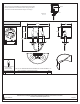
Figure 4
STEP 4 Install Fixture Body-
A. Carefully tuck all wires into the
outlet box and position the
backplate of fixture body (C)
over the outlet box. Align the
holes in the backplate with the
mounting screws. Place caulk
(not supplied) into the
previously removed mounting
balls and then attach fixture
body (C) using the mounting
balls. Hand tighten until snug.
Mounting
Screw
C
Mounting
Ball
A
Backplate
Hex Nut and
Lock Washer
B
Shade
x1
D
Lock
Screw
x1
Mounting
Screw
C
Mounting
Ball
A
Backplate
Hex Nut and
Lock Washer
Figure 5
STEP 5 Install Shade-
A. Place Shade (B) over the
Fixture Body (C), line up the
hole on the Shade (B) and the
mounting hole on the
Backplate, secure by
threading Lock Screw (D)
onto the Backplate. Hand
tighten until sung.
D
B
C
Backplate