
Owners Manual

QUIETCOOLSYSTEMS.COM
16
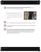
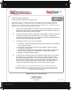
6. Attach the red leg wire from the timer to the top gold screw on the left of the switch. Finish up the
installation of the timer and switch and switch cover plate.
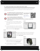
7. Begin wiring the your fan by opening up the handy box. Take off the wire nuts within the handy box.
Detach the green ground wire from the power cord. Remove the power cord. Re-attach the ground
screw and wire to the handy box. Cut your green ground wire in half and strip both sides.
(see Figure D)
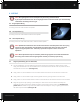
8. Feed the 2 wire Romex from your timer into the handy box. Feed the 2 wire Romex from your power
source into the handy box.
STL PRO-2.5X Wiring
Feed the 2 wire Romex from your switch into the handy box. Tape the white wire on this end of the
Romex. Tie the yellow & black wire together for high speed. Tie the red and taped white wire together
for low speed.
STL PRO-3.3X Wiring
Feed the 2 wire Romex from your switch into the handy box. Tape the white wire on this end of the
Romex. Tie the blue & black wire together for high speed. Tie the red and taped white wire together
for low speed.
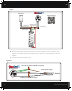
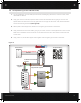
Power
Timer
Tie All Ground & Bare Copper Wires Together
Whole House Fan
14-2 Wire
14-2 Wire
Switch
14-2 Wire
Low Speed
High Speed
White Common Wires Together
Black Wires Together
White - Marked w/ Tape
Black
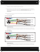
Power
Timer
Tie All Ground & Bare Copper Wires Together
Whole House Fan
14-2 Wire
14-2 Wire
Switch
14-2 Wire
Low Speed
High Speed
White Common Wires Together
Black Wires Together
White - Marked w/ Tape
Black
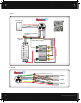
Power
Timer
Tie All Ground & Bare Copper Wires Together
Whole House Fan
14-2 Wire
14-2 Wire
Switch
14-2 Wire
Low Speed
High Speed
White Common Wires Together
Black Wires Together
White - Marked w/ Tape
Black
Power
Timer
Tie All Ground & Bare Copper Wires Together
Whole House Fan
14-2 Wire
14-2 Wire
Switch
14-2 Wire
Low Speed
High Speed
White Common Wires Together
Black Wires Together
White - Marked w/ Tape
Black
Figure D (STL PRO-2.5X)
Figure E (STL PRO-3.3X)