
User guide


8-Pin DIN Connector Pinout
C-3
C
connecting supports automatic MDI/MDI-X operation, you can use either
“straight-through” or “crossover” cable.
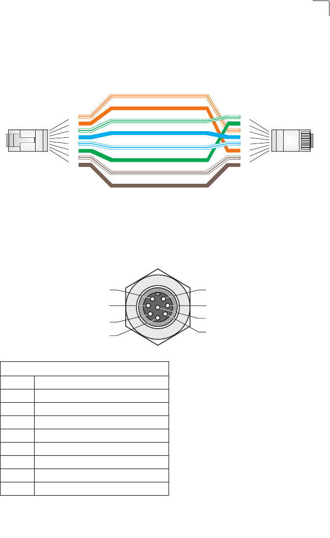
8-Pin DIN Connector Pinout
The Ethernet cable from the power injector connects to an 8-pin DIN connector on
the wireless bridge. This connector is described in the following figure and table.
8-Pin DIN Ethernet Port Pinout
Pin Signal Name
1 Transmit Data plus (TD+)
2 Transmit Data minus (TD-)
3 Receive Data plus (RD+)
4 +48 VDC power
5 +48 VDC power
6 Receive Data minus (RD-)
7 Return power
8 Return power
Note: The “+” and “-” signs represent the polarity of the
wires that make up each wire pair.
White/Orange Stripe
Orange
White/Green Stripe
1
2
3
4
5
6
7
8
1
2
3
4
5
6
7
8
EIA/TIA 568B RJ-45 Wiring Standard
10/100BASE-TX Crossover Cable
End A
End B
Green
Blue
White/Blue Stripe
Brown
White/Brown Stripe
1
7
2
3
4
5
8
6