645 Lemonwood Dr. Santa Paula, CA, 93060 USA Toll Free: (888) 262-3880 Tel: (805) 421-5114 quickjack.com QuickJack™ Portable Car Jack Setup and Operation Manual Manual P/N 5900959 — Manual Revision J3 — Released Oct. 2019 Models: • BL-3500SLX BL-6000XLT • BL-5000SLX BL-5000EXT • BL-7000SLX BL-7000EXT Visit http://www.quickjack.com/setup.html for a video demonstration of QuickJack setup. QuickJack is designed and engineered by BendPak Inc. in Southern California, USA. Made in China.
Manual. QuickJack™ Portable Car Jack, Setup and Operation Manual, P/N 5900959, Manual Revision J3, Released October 2019. Copyright. Copyright © 2019 by BendPak Inc. All rights reserved. You may make copies of this document if you agree that: you will give full attribution to BendPak Inc., you will not make changes to the content, you do not gain any rights to this content, and you will not use the copies for commercial purposes. Trademarks.
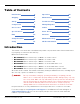
Table of Contents Introduction 3 Operation 35 Shipping 5 Maintenance 48 Safety 5 Troubleshooting 50 Components 8 Wiring Diagrams 52 Accessories 10 Labels 53 Specifications 11 Parts Sheets 56 FAQ 13 ALI Store 76 Setup Checklist 14 Maintenance Log 77 Setup 15 CE Documentation 78 Introduction This manual covers all models of the QuickJack portable car jack, which makes Vehicle maintenance in your garage or at the track fast and easy.
IMPORTANT! PLEASE READ Only raise your QuickJack Frames with a Vehicle on them! The QuickJack is designed and engineered to be used with the weight of a Vehicle on it. You should only raise the QuickJack Frames with the weight of a Vehicle on them, even the very first time you use them (with the exception of bleeding the Hydraulic Cylinders). There is simply no reason to raise your QuickJack Frames unless there’s a Vehicle on them.
Shipping Your QuickJack was carefully checked before shipping. Nevertheless, you should thoroughly inspect the shipment before you sign to acknowledge that you received it. When you sign the bill of lading, it tells the carrier that the items on the invoice were received in good condition. To protect yourself, do not sign the bill of lading until after you have inspected the shipment.
10. Keep hair, loose clothing, fingers, and all parts of your body away from moving parts. 11. To reduce the risk of electric shock, do not use on wet surfaces or expose to rain. 12. Use only as described in this manual. Use only manufacturer’s recommended attachments. 13. Always wear safety glasses. Everyday glasses only have impact resistant lenses, they are not safety glasses. 14. To reduce the risk of injury, close supervision is necessary when this product will be used around children. 15.
• • • • • • Floor surface must be dry, flat, and have a minimum compressive strength of 500 PSI. Avoid using an extension cord; they can overheat. If you must use an extension cord, make sure it is No. 14 AWG minimum. Take care locating the electrical cable and Hydraulic Hoses; you do not want them driven over or stepped on. Clear the area if a Vehicle is in danger of falling off the jack. Make sure both Lock Bars are engaged before nearing an elevated Vehicle.
Components QuickJack components include: • Two QuickJack Frames. The Frames, working together, raise and lower Vehicles. The two Frames are not interchangeable. The Lock Bars, described below, must be on the outside when you orient the Frames. Your QuickJack has a left Frame and a right Frame.
• • • Hydraulic Cylinder and Air Cylinder. Each QuickJack Frame has one Hydraulic Cylinder and one Air Cylinder. The Hydraulic Cylinder is welded to the Frame and the Air Cylinder is welded to the Hydraulic Cylinder. The Hydraulic Cylinder receives Hydraulic Fluid from the Power Unit, which is used to move the Frames up and down. The Air Cylinder acts like an air spring, which means they assist in lowering the Frames.
Accessories SUV and Light Truck Adapter Kit The optional SUV and Light Truck Adapter Kit increases the service capability of your QuickJack by providing stackable Lift Blocks that mount inside the Receiver Trays. The Adapter Kit is available for Models BL-5000SLX/EXT and BL-7000SLX/EXT.
Specifications Model BL-3500SLX BL-5000SLX BL-7000SLX Lifting capacity 3,500 lbs / 1,588 kg 5,000 lbs / 2,268 kg 7,000 lbs / 3,175 A Lowered height (frame only) 3" / 76 mm 3" / 76 mm 3.6" / 91 mm B Height, frame only * 16.5" / 419 mm 17.6" / 447 mm 18.2" / 462 mm C Height, 2" blocks 17" / 432 mm 18.4" / 467 mm 18.6" / 471 mm D Height, 3" blocks 18.5" / 470 mm 19.2" / 487 mm 19.4" / 493 mm E Height, stacked blocks 20" / 508 mm 21.3" / 542 mm 21.6" / 548 mm F Frame width 10.
Model BL-6000XLT BL-5000EXT BL-7000EXT Lifting capacity per pair 6,000 lbs / 2,722 kg 5,000 lbs / 2,268 kg 7,000 lbs / 3,175 kg A Collapsed height 3.6" / 91 mm 3" / 76 mm 3.6" / 91 mm B Height, no blocks * 18.2" / 462 mm 17.6" / 447 mm 18.2" / 462 mm C Height, small blocks 18.6" / 471 mm 18.4" / 467 mm 18.6" / 471 mm D Height, tall blocks 19.4" / 493 mm 19.2" / 487 mm 19.4" / 493 mm E Height, stacked blocks 21.6" / 548 mm 21.3" / 542 mm 21.6" / 548 mm F Frame width 12.
Frequently Asked Questions Question: What kinds of Vehicles can I raise using my QuickJack? Answer: A wide variety. The two main criteria are: is the Vehicle under the weight capacity of your QuickJack and do the QuickJack’s Lift Blocks hit the Vehicle’s factory-recommended Lifting Points? If the answers are yes, and for most Vehicles the answers are yes, then you can raise the Vehicle.
Setup Checklist Following are the steps needed to install a QuickJack. Perform them in the order shown. ☐ 1. Review the setup Safety Rules. ☐ 2. Make sure you have the necessary Tools. ☐ 3. Select the setup Site. ☐ 4. Unpack the Components that came with the QuickJack. ☐ 5. Make sure there is adequate Clearance on all sides and above. ☐ 6. Locate the QuickJack Assembly Kit. ☐ 7. Locate and examine the Air and Hydraulic Cylinders. ☐ 8. Install the Hydraulic Elbow Fittings. ☐ 9.
Setup This section describes how to set up your QuickJack. ⚠ WARNING Use only the factory-supplied parts that came with your QuickJack. If you use parts from a different source, you void your warranty and compromise the safety of everyone who sets up or uses the QuickJack. If you are missing parts, visit quickjack.com/support or contact QuickJack Technical Support at support@quickjack.com, (888) 262-3880, or (805) 933-9970.
Selecting a Site Keep the following in mind when selecting a site for your QuickJack: • • Enough space. Make sure there is adequate space for the QuickJack and the Vehicles you will be raising. Radial Shift. When you raise your QuickJack with a Vehicle on it, the geometry of the Frames moves the Vehicle up at a slight angle, towards the sticker end of the QuickJack; refer to the graphic in Unpacking. Radial shift is always towards the sticker end of the QuickJack, no matter which way the Vehicle is facing.
Unpacking Open the boxes and arrange the QuickJack components where you will be setting them up. ⚠ WARNING ⚠ CAUTION QuickJack™ Portable Car Jack Your two QuickJack Frames are similar, but they are not interchangeable. Always line up your Frames as parallel to each other as the Lifting Points will allow, with the Lock Bars on the outside, as shown below. Be sure to route the Short Hydraulic Hoses under the QuickJack Frames.
Clearances Not necessarily to scale. Not all components shown. Vehicle approach must be opposite Power Unit. Do not drive Vehicle on Hydraulic Hoses, Power Unit, or QuickJack Frames. QuickJack™ Portable Car Jack 18 P/N 5900959 — Rev. J3 — Oct.
QuickJack Assembly Kit Many of the items you will be using during initial setup come in the QuickJack Assembly Kit, which is a clear plastic container included in your QuickJack packaging.
Installing the Hydraulic Elbow Fittings You need to install one Hydraulic Elbow Fitting on each Hydraulic Cylinder. To install a Hydraulic Elbow Fitting: 1. Remove the shipping plug from the Hydraulic Cylinder Port using a 6 mm hex key. 2. Get an Hydraulic Elbow Fitting from the QuickJack Assembly Kit; screw the O-ring fitting end into the Hydraulic Cylinder Port.
Preparing the Short Hydraulic Hoses Your QuickJack comes with two Short Hydraulic Hoses: • • Female end. Attach directly to the Hydraulic Elbow Fitting on the Hydraulic Cylinder. You do not need to add a fitting to this end of the Short Hydraulic Hose. Male end. Install a male Quick-Connect Fitting to the male end. To set up and connect the Short Hydraulic Hoses: 1. Locate both Short Hydraulic Hoses and remove their protective caps. 2.
3. Attach one male Quick-Connect Fitting from the QuickJack Assembly Kit to the male threaded fitting end of the Short Hydraulic Hose; tighten to 23 to 25 lbf-ft / 31 to 34 N-m. To tighten, use one wrench to hold the Male threaded end in place and a second wrench on the Male Quick-Connect Fitting. Do the same for the other Short Hydraulic Hose. 4. Connect the female end of the Short Hydraulic Hose to the male connector on the Hydraulic Elbow Fitting; tighten to 23 to 25 lbf-ft / 31 to 34 N-m.
Routing the Short Hydraulic Hoses After connecting the Short Hydraulic Hoses to the Hydraulic Elbow Fitting on the Hydraulic Cylinder, make sure to route them under the side of the QuickJack Frame. ⚠ CAUTION If you mistakenly route a Short Hydraulic Hose over the QuickJack Frame, the QuickJack will not work correctly and you could damage the hose and/or cause the Vehicle on the QuickJack to become unstable.
Preparing and Connecting the Long Hydraulic Hoses Your QuickJack comes with two Long Hydraulic Hoses: • • One end attaches to the Short Hydraulic Hose The other end attaches to the Power Unit Both ends require the installation of a female Quick-Connect Fitting. To prepare and connect your Long Hydraulic Hoses: 1. Locate both Long Hydraulic Hoses and remove their protective caps. 2. Wrap all four threaded ends with Thread Seal Tape.
Pressurizing the Air Cylinders The Air Cylinders (one on each QuickJack Frame) need to be pressurized before you can use your QuickJack. Air Cylinders help push the QuickJack Frames down. Note that the valve stems on the Air Cylinders are installed at the factory. Make sure the QuickJack Frames are fully lowered when you pressurize the Air Cylinders. To pressurize the Air Cylinders: 1.
Find a Location for the Power Unit Your Power Unit must be located near the QuickJack Frames. Note: Some Power Units come with a carrier and handle, some with just a handle. They work the same. Based on the combined length of the Short and Long Hydraulic Hoses, your Power Unit should be about 10 to 12 feet away from your QuickJack Frames and out of the way of the Vehicles you will be driving on to and off of the QuickJack.
Connect the Power Unit to a Power Source Your Power Unit must also be located near an appropriate power source. Refer to the manufacturer’s information tag on your Power Unit for current and wattage information for your specific unit. Power Sources for VAC Power Units If you are using a 110 or 220/240 VAC Power Unit with your QuickJack, connect it to an appropriate power source. 110 VAC Power Unit Drawing not necessarily to scale. Some Power Units may be slightly different.
Power Sources for 12 VDC Power Units If you are using a 12 VDC Power Unit with your QuickJack, you can connect it to a Vehicle battery. Refer to Using the 12 VDC Power Unit for usage information. 12 VDC Power Unit Drawing not necessarily to scale. Some Power Units may be slightly different. Keep the following in mind: • • • Connect your 12 VDC Power Unit directly to a 12-volt power source. The minimum requirement for Jumper Cables is 7 gauge / 10 mm.
Filling the Hydraulic Fluid Reservoir on the Power Unit The Hydraulic Fluid Reservoir must be filled with Hydraulic Fluid or Automatic Transmission Fluid before you begin operation of the QuickJack. When you receive it, the Fluid Reservoir is empty. The Power Unit will not work correctly until it is filled with approved fluids. ⚠ CAUTION If you use the QuickJack without fluid in the reservoir, you could damage the Power Unit.
Check the Breather Valve If your Power Unit has a Reservoir Cap with a Breather Valve, you need to loosen the Breather Valve before using the Power Unit. It ships tightened, so that no contaminants will get inside. If your Power Unit has a Self-Venting Reservoir Cap (see drawing below), you do not need to loosen it. To check the Breather Valve: 1. Determine what Breather Valve is on your Power Unit: • Reservoir Cap, with Breather Valve. The Breather Valve comes from the factory tightened.
Bleeding the Hydraulic Cylinders Bleeding the Hydraulic Cylinders removes air from the Hydraulic System. If you have air in the Hydraulic System, you can experience shaking, jerking, one frame rising faster than the other, and so on during raising and lowering. This does not damage the QuickJack or the Hydraulic Cylinder, but it is not the normal smooth experience you should be getting.
6. Using the Pendant Control, raise and then lower both Frames about 8 in / 203 mm or so off the ground (do not pass the First Locking Position) three times. Raising and lowering the Frames moves Hydraulic Fluid into the Hydraulic System and pushes air towards the Bleeder Screws. Note: Without the weight of a Vehicle on them, the QuickJack Frames may lower unevenly and slower than normal. 7. Put a clean rag under the Bleeder Screw on the Hydraulic Cylinder you are going to bleed first.
Final Checklist Before Operation Make sure these things have been done before using your QuickJack: • • • • • Review the Setup Checklist to make sure all steps have been performed. Make sure the Power Unit is getting power from the power source. Check the Hydraulic Fluid Reservoir; it must be full of approved Hydraulic Fluid or automatic transmission fluid. You can harm the motor by running it without enough fluid. Check the Hydraulic System for leaks.
5. Put a Vehicle into place. Do not raise your QuickJack without the weight of a Vehicle. 6. Position the Lift Blocks in the Receiver Trays for the Vehicle you are going to raise. Be sure to use the factory-recommended Lifting Points for the Vehicle. 7. Press Up on the Pendant Control for a couple of seconds. After a few seconds, the QuickJack Frames will start moving up. As this is the first use, it takes a couple of seconds for the Hydraulic Hoses to fill with fluid.
Operation This section describes how to operate your QuickJack. This manual must delivered to the owner/user/employer and be kept near the QuickJack. QuickJack recommends using Vehicle Lifting Points for Frame-Engaging Lifts for proper positioning of Vehicles on your QuickJack. It shows the factory-recommended Lifting Points for a wide variety of Vehicles. It is available on the ALI website.
About Lift Blocks When raising a Vehicle with your QuickJack, the Vehicle should not touch the QuickJack Frames. Instead, they should touch the Lift Blocks that are sitting in the QuickJack’s Receiver Trays. There are three types of Lift Blocks available: • • • Medium/Tall. Four Medium and four Tall Lift Blocks are included with each QuickJack. You can stack one Medium on one Tall, but no more than that; make sure they are centered under the Lifting Points. Pinch Weld.
Special QuickJack Warnings There are two special cases with QuickJack of which you need to be aware: • Do not raise QuickJack Frames without a Vehicle on them. QuickJack Frames are designed and engineered to be used with the weight of a Vehicle on them. You should only raise the QuickJack Frames with the weight of a Vehicle on them, even the very first time you use them. The only exception to this rule is if you are bleeding the Hydraulic Cylinders.
Positioning the Lift Blocks and Frames ⚠ WARNING Always position the two QuickJack Frames as close to parallel as the Lifting Points of the Vehicle allow; load stability can be compromised if they are too far off from parallel. There are two methods for positioning your QuickJack Frames: • • Outside in: Drive the Vehicle to the desired location, position the QuickJack Frames outside the Vehicle on different sides and between the wheels.
Raising the QuickJack Frames QuickJack Frames have two locking positions, called First Locking Position and Top Locking Position. When you raise the QuickJack Frames, always engage (lock) the Frames on either the First Locking Position or the Top Locking Position, or lower them back down to the ground.
If the Lock Bar Bolt is too tight, it does not allow the Lock Bar to move freely in the Lock Channel. This is a safety issue; the QuickJack locks cannot be engaged unless each Lock Bar is moving freely in its Lock Channel. If the Lock Bar moves up with the Vehicle as it is raised (as shown above on the right), it cannot lock. ⚠ WARNING The Lock Bar must be moving freely in the Lock Channel. If it is not, the QuickJack cannot be put into a safe, locked position.
19. Visually check to make sure both QuickJack Frames are engaged on the same locking position. Not necessarily to scale. Not all components shown. Shows Release Cam and Lock Bar in Locked Position. ⚠ WARNING Before doing anything else (like starting work on the Vehicle or leaving the area), visually confirm that both QuickJack Frames are on the same locking positions and that all Lift Blocks are in contact with the factory-recommended Lifting Points of the Vehicle.
Lowering the Frames from the First Locking Position Lowering the QuickJack’s Frames from the First Locking Position is different from lowering them from the Top Locking Position, so it is described separately. ⚠ WARNING When lowering QuickJack Frames, make sure the Lock Bar and the Release Cam stay in their Lock Channel. If they get knocked sideways they can get stuck on the rail of the Lock Channel, which results in the QuickJack not lowering correctly.
Do not lower the Release Cam / Lock Bar if the Release Cam is in the Up position, as shown below. The Release Cam needs to be in the Down position, as shown in the drawing on the previous page. If the Release Cam is in the Up position, carefully use your hand to move it to the Down position. Not necessarily to scale. Not all components shown. Release Cam shown in the Up position, which must be changed to the Down position before lowering.
Lowering the Frames from the Top Locking Position Lowering the QuickJack’s Frames from the Top Locking Position is different from lowering them from the First Locking Position, so it is described separately. ⚠ WARNING When lowering QuickJack Frames, make sure the Lock Bar and the Release Cam stay in their Lock Channel. If they get knocked sideways they can get stuck on the rail of the Lock Channel, which results in the QuickJack not lowering correctly.
Using the 12 VDC Power Unit The 12 VDC Power Unit lets you power your QuickJack using a Vehicle Battery and a pair of Jumper Cables, giving you the flexibility to use your QuickJack in a wide variety of locations. The following drawing shows how to connect the 12 VDC Power Unit to a Vehicle Battery. Not to scale. Not all components shown. The Jumper Cables and the Vehicle Battery are not supplied with the 12 VDC QuickJack Power Unit.
The following procedure applies only to the 12 VDC QuickJack Power Unit; none of the other QuickJack Power Units can be used with a Vehicle Battery. ⚠ WARNING QuickJack recommends wearing safety glasses and removing all jewelry before connecting the 12 VDC QuickJack Power Unit to a Vehicle Battery. If metal touches in the wrong place, it could cause a short circuit that results in an exploded battery, ruined Vehicle computer, burned fingers, and/or battery acid burns.
• • • • • • • • • • If you purchased the SUV and Light Truck Adapter Kit, the square pieces go rubber-down in the Receiver Trays on the QuickJack Frames. You can then put the round stackable adapter in the hole on the top of the square piece either by itself or combined with the extension. Visually inspect your QuickJack before each use. Do not use it if you find any damage or severe wear. Do not rock the Vehicle while it is raised or remove heavy items that could cause excessive weight shift.
Maintenance Refer to ANSI/ALI ALIS Standard (R2015) Safety Requirements for Installation and Service of Automotive Lifts for more information about safely servicing your QuickJack. ⚠ WARNING: Remove power from your QuickJack before performing any maintenance! The QuickJack must be de-energized and you must take steps to make sure that it cannot be re-energized until all maintenance is complete. Reorder labels and worn, damaged, or broken parts from quickjack.com/replacementparts.html.
About Outdoor Operation Your QuickJack is approved for indoor installation and use only. Outdoor installation is prohibited. Your QuickJack is portable, however, so if you end up taking it outdoors, remember to protect it from the weather (for example, from falling dirt, rain, sleet, and snow). Here are some additional things to consider if you end up taking your QuickJack outside: • • • Extreme environmental conditions must be avoided.
Troubleshooting This section describes how to troubleshoot your QuickJack. ⚠ WARNING Note: Only use factory-supplied parts as replacement parts. If you use parts from a different source, you void your warranty and compromise the safety of everyone who uses the QuickJack. If your QuickJack is not functioning correctly, you must stop using it until it is fixed. Important: All repair work must be done by qualified personnel. Issue Action to Take Frames do not go up or down.
Frames at Full Height with No Load The issue is that the QuickJack is designed and engineered to work with the weight of a Vehicle on it. If there is no Vehicle on the Frames at full height, the QuickJack can occasionally get stuck. Do not raise the QuickJack Frames unless there is the weight of a Vehicle on them. Methods that have fixed this issue include: • • Use lifting equipment to get weight onto the QuickJack Frames. Reduce the hydraulic force that is holding the QuickJack Frames.
Wiring Diagrams 12 VDC Wiring Diagram Down Up SB2 SB1 3 2 Red + White Remote Control 1 Black Start Switch – Power Unit M Battery Ground Motor Start Switch Coil Solenoid Valve Coil 208-230 VAC Wiring Diagram Make sure to follow the 208-230 VAC electrical rules for the country in which you are using the unit. QuickJack™ Portable Car Jack 52 P/N 5900959 — Rev. J3 — Oct.
Labels QuickJack™ Portable Car Jack 53 P/N 5900959 — Rev. J3 — Oct.
QuickJack™ Portable Car Jack 54 P/N 5900959 — Rev. J3 — Oct.
QuickJack™ Portable Car Jack 55 P/N 5900959 — Rev. J3 — Oct.
Parts Sheets QuickJack™ Portable Car Jack 56 P/N 5900959 — Rev. J3 — Oct.
QuickJack™ Portable Car Jack 57 P/N 5900959 — Rev. J3 — Oct.
QuickJack™ Portable Car Jack 58 P/N 5900959 — Rev. J3 — Oct.
QuickJack™ Portable Car Jack 59 P/N 5900959 — Rev. J3 — Oct.
QuickJack™ Portable Car Jack 60 P/N 5900959 — Rev. J3 — Oct.
QuickJack™ Portable Car Jack 61 P/N 5900959 — Rev. J3 — Oct.
QuickJack™ Portable Car Jack 62 P/N 5900959 — Rev. J3 — Oct.
QuickJack™ Portable Car Jack 63 P/N 5900959 — Rev. J3 — Oct.
QuickJack™ Portable Car Jack 64 P/N 5900959 — Rev. J3 — Oct.
QuickJack™ Portable Car Jack 65 P/N 5900959 — Rev. J3 — Oct.
QuickJack™ Portable Car Jack 66 P/N 5900959 — Rev. J3 — Oct.
QuickJack™ Portable Car Jack 67 P/N 5900959 — Rev. J3 — Oct.
QuickJack™ Portable Car Jack 68 P/N 5900959 — Rev. J3 — Oct.
QuickJack™ Portable Car Jack 69 P/N 5900959 — Rev. J3 — Oct.
QuickJack™ Portable Car Jack 70 P/N 5900959 — Rev. J3 — Oct.
QuickJack™ Portable Car Jack 71 P/N 5900959 — Rev. J3 — Oct.
QuickJack™ Portable Car Jack 72 P/N 5900959 — Rev. J3 — Oct.
QuickJack™ Portable Car Jack 73 P/N 5900959 — Rev. J3 — Oct.
QuickJack™ Portable Car Jack 74 P/N 5900959 — Rev. J3 — Oct.
QuickJack™ Portable Car Jack 75 P/N 5900959 — Rev. J3 — Oct.
Automotive Lift Institute (ALI) Store You probably checked the ALI’s Directory of Certified Lifts (www.autolift.org/ali-directory-ofcertified-lifts/) before making your most recent Lift purchase, but did you know the ALI Store (www.autolift.
Maintenance Log QuickJack™ Portable Car Jack 77 P/N 5900959 — Rev. J3 — Oct.
CE Documentation
Declaration of Conformity The equipment that accompanies this declaration is in conformity with EU Directive: 2006/42/EC Machinery Directive Manufacturer BendPak Inc. 1645 Lemonwood Dr. Santa Paula, CA 93060 USA A copy of the Technical file for this equipment is available from: CCQS UK Ltd., Level 7, Westgate House, Westgate Rd.
1645 Lemonwood Drive Santa Paula, CA, 93060 USA © 2019 BendPak Inc. All rights reserved. bendpak.