
QF4A512-DK Users Guide - Quickfilter
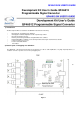


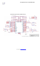


Figure 2 shows the actual test points that connect the signal path through the prototyping area. By removing for example
C2, Channel 1 is still single ended since C1 has a signal path to ground, however the input path now comes into BNC
connector J1 to TP4. The designer can now add circuitry from TP4 and connect it’s output to TP3 going into the
QF4A512’s channel 1.
3) Changing the default configuration of AC coupled single ended:
Changing the default configuration of AC coupled single ended to differential or DC coupled can be done by the following.
For differential applications the resistor R2 to ground can be removed see Figure 2. In this case Channel 1 is now
differential AC coupled. If DC coupling is desired C2 can be shorted. See application note QFAN004 for DC
measurement requirements which specifies a minimum 10K resistor in series. This resistor can be added by replacing R3
in channel 1 for single ended applications, or R1 and R3 for differential applications.
4) Input level protection scheme:
The QF4A512 development board was designed to be able to take large input voltages > the normal maximum 2Vpp. A
large input voltage of say 25Vpp AC will simple show a clipping square wave on Channel 1 when for example Zener diode
D1 turns on which is current limited by series resistor R1. This means the QF4A512 actually sees a 5.1Vpp square wave
coming into channel 1. This square wave is then further current limited by the 51 ohm resistor R2 going into the QF4A512.
This over voltage of 5.1 Volts turns on the internal protection diodes of the QF4A512 showing distortion on the FFT by
multiple harmonics. No damage occurs.
5) Running external target hardware using Quickfilter’s PC software:
The Designer can run external QF4A512 hardware by hooking up the external SPI interface to their target hardware. By
using CS2 Pin 13 on the header J5 and selecting “Use programming adapter board” in Quickfilter Pro software, CS2 is
selected and CS1 which goes to the on board QF4A512 U1 is shut off. A second method is manually removing zero ohm
resistor R16 which hooks CS1 to U1. In this case CS1 Pin 9 could be selected for the Chip Select control externally and
the Quickfilter software run normally.
SPI
J5
HEADER 7X2
Figure 3