
QF4A512-DK Users Guide - Quickfilter


Supplying Power:
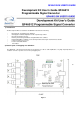
Figure 1 shows red circles for +4.5 Volts brought to the prototyping area, yellow circles for +3.3V, green for Ground, dark
blue for the test points, grey no connect, and black tied together as a 4 node bus (rev 2.4 boards only). Note that the +4.5V
can be increased to +5V directly off of the USB power by shorting diode D8 on the back side of the board. D8 was designed
to protect the USB power from someone adding too much external power through J7. In fact you could supply for example
+12V through J7, remove diode D8, and a +12Volt supply would be fed through the “+5V” prototyping area. The on board
regulators can handle the +12V drop to +3.3V and the USB power is protected. Adding additional power may be useful if
more than 60mA of power is needed for the prototyping area, or if a very clean supply is needed. For example a battery
pack could be connected to J7. See Page 5 of the schematics for a detailed power supply diagram.
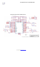
Adding circuits in the analog input stage:
Figure 1 shows Test points which are actually the connection points for signals coming into the prototyping area.
ANALOG INPUTS
Prototype
work,
Channels 1-4remove caps for
Protection
Z
ener Diodes
5V, 300mW
disconnect
R1 R61
CH 1
BNC
J1
CH 2
BNC
J2
CH 3
BNC
J3
CH 4
BNC
J4
100 1% 51.0 1%
Figure 2