
QF4A512-DK Users Guide - Quickfilter


QF4A512-DK USER’S GUIDE
Development Kit User’s Guide QF4A512
Programmable Signal Converter
1) Introduction
The Development Kit User’s Guide for the QF4A512 describes the following:
• Board Layout / Prototyping area definition.
• Changing the default configuration of AC coupled single ended.
• Input level protection scheme.
• Running external target hardware using Quickfilter’s PC software.
• Running Quickfilter’s hardware on the development board using an external microcontroller.
• Using an external clock source.
• List of Test Point Definitions.
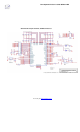
• Schematics.
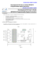
Figure 1
TOP
The QF4A512 – DK development board was designed to be able to add amplification, very high input impedance, o
r
excitation current for specific sensors in the prototyping area.
2) Board Layout / Prototyping area definition:
3"