REV 001a QNC CHC Chain Counter IT Pag. 3 MANUALE D’INSTALLAZIONE E USO CONTA CATENA QNC CHC EN Pag.
QNC CHC IT INDICE 1.0 - INFORMAZIONI SUL PRODOTTO..................................................................................Pag. 1.1 - Principali caratteristiche ............................................................................................Pag. 1.2 - Note importanti ..........................................................................................................Pag. 1.3 - Precauzioni per la sicurezza e l’uso ....................................................................
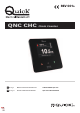
QNC CHC IT 1.0 - INFORMAZIONI SUL PRODOTTO Lo strumento QNC CHC permette di azionare il salpa ancora per salpare o calare l’ancora, fornendo la misura della catena calata. 1.1 - Principali caratteristiche • • • • • • • • • • • • • • • • Frontale in vetro. Display grafico da 3,5” IPS a colori ad elevata luminosità. Tasti funzione capacitivi. Profilo estremamente ridotto. Interfaccia utente multilingua. Funzione blocco tasti automatico. Funzione di discesa automatica. Funzione di allarme in salita.
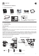
QNC CHC IT 1.0 - INFORMAZIONI SUL PRODOTTO 1.4 - Contenuto della confezione Conta catena QNC CHC Coperchio di protezione Kit sensore conta catena Viterie per il fissaggio Guarnizione DIMA FORATURA CHC- 3.5'' A A B D B 45° Cavo alimentazione e I/O 0,5 m mm inch 11,5 ø0''29⁄64 D 115 C A 1''57⁄64 B 48,1 C 100,2 3''15⁄16 D 71,5 2''13⁄16 Descrizione / Description DRILLING TEMPLATE B A B CHC- 3.
QNC CHC IT 2.0 - INSTALLAZIONE 2.2 - Installazione del magnete Smontare il barbotin dal salpa ancora (riferirsi al manuale d’uso del salpa ancora). Individuare la posizione più adatta dove praticare la sede per alloggiare il magnete seguendo questi criteri: • • • • La sede deve essere praticata in una zona non interessata dal passaggio della catena (zone esterne). La sede deve essere praticata preferibilmente nella zona dove il barbotin è più spesso (per non indebolirne la struttura).
QNC CHC IT 2.0 - INSTALLAZIONE 2.4 - Installazione dello strumento Lo strumento conta catena risponde agli standard EMC (compatibilità elettromagnetica) ma è richiesta una corretta installazione per non compromettere le proprie prestazioni e quelle degli strumenti posti nelle vicinanze. Per questo motivo lo strumento deve essere distante almeno: • 25 cm dalla bussola. • 50 cm da un qualsiasi apparecchio radio ricevente. • 1 m da qualsiasi apparato radiotrasmittente (escluso SSB).
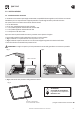
QNC CHC IT 2.0 - INSTALLAZIONE 2.4 - Installazione dello strumento • (Fig. 4) Inserire la guarnizione con il lato adesivo verso l’alto e applicarla allo strumento. Avvitare i 4 prigionieri alle boccole di fissaggio. • (Fig. 5) Inserire lo strumento nella sede. Da sotto il pannello inserire sui prigionieri 4 rondelle sagomate, 4 Grower e avvitare i 4 dadi. Fig. 4 Fig.
QNC CHC IT 2.0 - INSTALLAZIONE 2.5 - Collegamento elettrico Lo strumento conta catena risponde agli standard EMC (compatibilità elettromagnetica) ma è richiesta una corretta installazione per non compromettere le proprie prestazioni e quelle degli strumenti posti nelle vicinanze. Per questo motivo i cavi dello strumento devono essere distanti almeno: • 1 m dai cavi che trasportano segnale radio (escluso di radiotrasmittenti SSB). • 2 m dai cavi che trasportano segnale radio di radiotrasmittenti SSB.
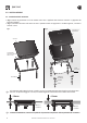
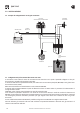
QNC CHC IT 2.0 - INSTALLAZIONE 2.6 - Esempio di collegamento di un singolo strumento UP UP DOWN BLU INTERRUTTORE FUSIBILE RAPIDO 4A COMANDO AUSILIARIO NERO CASSETTA TELERUTTORE/TELEINVERTITORE DOWN VERDE BIANCO SENSORE MARRONE BATTERIA 12/24 V CAVO ALIMENTAZIONE E I/O BARBOTIN QNC CHC 2.
QNC CHC IT 2.0 - INSTALLAZIONE 2.
QNC CHC IT 2.0 - INSTALLAZIONE 2.
QNC CHC IT 3.0 - FUNZIONAMENTO DELLO STRUMENTO 3.1 - PANORAMICA DEL QNC CHC La gestione dello strumento è affidata ad un’interfaccia utente che consente di: • • • • comandare la movimentazione del salpa ancora; visualizzare la lunghezza della catena calata; gestire i parametri di funzionamento; segnalare eventuali avvisi o allarmi. 3.2 - Descrizione dell’interfaccia utente L’interfaccia utente è composta da un display, tre tasti, un buzzer.
QNC CHC IT 3.0 - FUNZIONAMENTO DELLO STRUMENTO 3.
QNC CHC IT 3.0 - FUNZIONAMENTO DELLO STRUMENTO 3.6 - Azionamento elettrico del salpa ancora SALITA DISCESA VELOCITÀ: 15.0 m/min VELOCITÀ: 15.0 m/min SALITA MENU SALITA DISCESA Salpare l'ancora Per salpare l'ancora premere il tasto fino alla posizione desiderata dopodiché rilasciare il tasto. p MENU DISCESA Calare l’ancora Per calare l’ancora premere il tasto fino alla posizione desiderata dopodiché rilasciare il tasto.
QNC CHC IT 3.0 - FUNZIONAMENTO DELLO STRUMENTO 3.9 - Descrizione del menu icone 16 HOME Uscita dal menu e ritorno alla schermata principale. AZZERA CONTATORE Azzeramento della misura della catena calata. BLOCCO TASTI AUTOMATICO Impostazione del tempo di blocco automatico dei tasti. IMPOSTAZIONE DISCESA AUTOMATICA Questa funzione permette di calare l’ancora automaticamente alla profondità impostata. GIORNO/NOTTE Scelta della modalità giorno/notte.
QNC CHC IT 4.0 - CONFIGURAZIONE DELLO STRUMENTO 4.1 - Configurazione di base dello strumento F F Lo strumento necessita, per funzionare adeguatamente, dell’inserimento dei dati corretti riguardanti GIRO BARBOTIN e NUMERO DI MAGNETI. Accertarsi di aver inserito correttamente i dati relativi al proprio salpa ancora (vedere paragrafo “Misurazione della circonferenza del barbotin” a pag. 19). Per poter procedere all’inserimento dei dati, è necessario che la misura della catena calata sia uguale a zero (0.
QNC CHC IT 4.0 - CONFIGURAZIONE DELLO STRUMENTO 4.
QNC CHC IT 4.0 - CONFIGURAZIONE DELLO STRUMENTO 4.5 - Sleep mode La funzione SLEEP MODE pone lo strumento in uno stato di basso consumo. Rimane attivo in background il rilevamento della misura della catena calata. Mantenere premuto il tasto VELOCITÀ: 0 m/min fino allo spegnimento del display (circa 5 secondi di pressione). 4.
QNC CHC IT 5.0 - MANUTENZIONE Prima di effettuare operazioni di manutenzione o pulizia, rimuovere l’alimentazione dello strumento. Per assicurare il funzionamento ottimale dello strumento verificare, una volta all'anno, i cavi e le connessioni elettriche. Pulire il frontale del QNC CHC con un panno morbido inumidito di acqua. Non utilizzare prodotti chimici o abrasivi per pulire lo strumento. 6.
QNC CHC EN INDEX 1.0 - INFORMATION ABOUT THE PRODUCT.........................................................................Page 1.1 - Main characteristics ..................................................................................................Page 1.2 - Important notes ..........................................................................................................Page 1.3 - Precautions for safety and use.................................................................................
QNC CHC EN 1.0 - INFORMATION ABOUT THE PRODUCT The instrument QNC CHC allows the windlass to be activated to get the anchor aweigh or lower the anchor providing the measure of the chain lowered. 1.1 - Main characteristics • • • • • • • • • • • • • • • • Glass front. IPS 3.5” high-brightness colour graphic display. Capacitive function keys. Very small profile. Multi-language user interface. Automatic locked keys function. Automatic lowering function. Up alarm function.
QNC CHC EN 1.0 - INFORMATION ABOUT THE PRODUCT 1.4 - Contents of the packaging Chain counter QNC CHC Protective cover Chain counter sensor kit Screws for fastening Gasket DIMA FORATURA CHC- 3.5'' A A B D B 45° Power supply cable and I/O 0.5 m mm inch 11,5 ø0''29⁄64 D 115 C A 1''57⁄64 B 48,1 C 100,2 3''15⁄16 D 71,5 2''13⁄16 Descrizione / Description DRILLING TEMPLATE B A B CHC- 3.
QNC CHC EN 2.0 - INSTALLATION 2.2 - Installing the magnet Take the gypsy off the windlass (consult the windlass user’s manual). Find the spot most suitable for the magnet housing based on the following criteria: • • • • The magnet should not be installed in an area that the chain passes through (outer areas). The housing should be preferably made in the area where the gypsy is thickest (in order not to weaken the structure).
QNC CHC EN 2.0 - INSTALLATION 2.4 - Instrument installation The chain counter meets EMC standards (electromagnetic compatibility). In any case correct installation is fundamental in order not to affect its performance or interfere with operation of instruments found near it. For this reason the chain counter must be at least: • 25 cm from the compass. • 50 cm from any radio receivers. • 1 m from any radio transmitters (except for SSB). • 2 m from any SSB radio transmitters. • 2 m from the radar beam path.
QNC CHC EN 2.0 - INSTALLATION 2.4 - Instrument installation • (Fig. 4) Insert the gasket with the adhesive side facing up and apply it to the instrument. Screw the 4 stud bolts to the fixing bushes. • (Fig. 5) Fit the instrument in its seat. Insert 4 shaped washers, 4 grower washers and 4 nuts to the stud bolts from beneath the panel. Fig. 4 Fig. 5 PROTECTIVE COVER QNC CHC GASKET WITH ADHESIVE SIDE FACING UP 4 HOLES Ø 11.
QNC CHC EN 2.0 - INSTALLATION 2.5 - Electric connections The chain counter meets EMC standards (electromagnetic compatibility). In any case correct installation is fundamental in order not to affect its performance or interfere with operation of instruments found near it. For this reason the cables must be at least: • 1 m from cables that transmit radio signals (except for SSB radio transmitters). • 2 m from cables that transmit SSB radio transmitter signals.
QNC CHC EN 2.0 - INSTALLATION 2.6 - Example of connection of a single instrument UP UP DOWN BLUE SWITCH FAST-BLOW FUSE 4A AUXILIARY COMMAND BLACK CONTACTOR/REVERSING CONTACTOR BOX DOWN GREEN WHITE BROWN BATTERY 12/24 V SENSOR POWER SUPPLY CABLE AND I/O GYPSY QNC CHC 2.7 - Connection of several instruments to the same CAN network The instrument is equipped with a CAN bus data interface that allows several instruments to be connected with each other for information exchange (CAN network).
QNC CHC EN 2.0 - INSTALLATION 2.
QNC CHC EN 2.0 - INSTALLATION 2.9 - CHC CAN bus network components 3-WAY M-M-M JUNCTION BACKBONE / DROP CABLE CODE DESCRIPTION FCPCHTCNMMM0A00 PCS/CHC3 TCN MMM T CAN M-M-M CONNECTOR 3-WAY M-M-F JUNCTION FCPCHTCNFMM0A00 PCS/CHC3 TCN FMM T CAN F-M-M CONNECTOR 2-WAY M-M JUNCTION FCPCHMMJMM00A00 CODE DESCRIPTION FCPCHEX00500A00 PCS/CHC3 EX005 CAN EXTENSION 0.
QNC CHC EN 3.0 - INSTRUMENT OPERATION 3.1 - QNC CHC OVERVIEW The instrument is managed by a user interface that allows you to: • • • • control windlass movements; display length of the chain lowered; manage operating parameters; report any warnings or alarms. 3.2 - Description of the user interface The user interface consists of a display, three keys and a buzzer. Graphic display 320 x 240 pixels Displays the length of the chain lowered, system status, operating parameters and other information.
QNC CHC EN 3.0 - INSTRUMENT OPERATION 3.4 - Main screen Once the initialization procedure has been completed, the main window is displayed: Sensor status Icon area and status line SPEED: 0 m/min Counting area Info area DOUBLE TOUCH TO UNLOCK This screen is divided into the following areas: Icon area and status line This area shows messages on instrument status, chain speed, and any problem reports.
QNC CHC EN 3.0 - INSTRUMENT OPERATION 3.6 - Electric Windlass operation CHAIN UP CHAIN DOWN SPEED: 15.0 m/min SPEED: 15.0 m/min CHAIN UP MENU CHAIN UP CHAIN DOWN Getting the anchor aweigh To get the anchor aweigh, press and hold desired position, then release the key. p key until the MENU CHAIN DOWN Lowering the anchor To lower the anchor, press and hold desired position, then release the key.
QNC CHC EN 3.0 - INSTRUMENT OPERATION 3.9 - Icon menu description 34 HOME Quit the menu and return to the main screen. RESET COUNTER Reset the measure of the chain lowered. AUTOMATIC KEY LOCK Setting the automatic key locking time. AUTODOWN SETTING This function allows lowering the anchor automatically to the set depth. DAY/NIGHT Selection of day/night mode. USER SETTINGS Access to user customised settings submenu. ADVANCED SETTINGS Access to instrument advanced settings submenu.
QNC CHC EN 4.0 - INSTRUMENT CONFIGURATION 4.1 - Configuration according to the instrument F F In order to work properly, the instrument requires to enter the correct data about GYPSY LAP and NUMBER OF MAGNETS. Make sure that data about your windlass have been correctly entered (point 4.6 “Gypsy circumference measurement” on page 37). To enter data, the measure of the lowered chain must be equal to zero (0.0). 4.
QNC CHC EN 4.0 - INSTRUMENT CONFIGURATION 4.
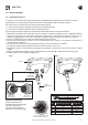
QNC CHC EN 4.0 - INSTRUMENT CONFIGURATION 4.5 - Sleep mode SLEEP MODE function sets the instrument to a low consumption status. The detection of lowered chain measurement remains active in the background. Press and hold SPEED: 0 m/min key until the display is off (approx. 5 seconds). 4.6 - Gypsy circumference measurement To determine the chain length obtained with each gypsy lap, proceed as follows: • Mark a reference on the chain and the gypsy on the main axis.
QNC CHC EN 5.0 - MAINTENANCE Before carrying out maintenance or cleaning operations, cut off power supply to the instrument. To ensure optimal operation of the instrument, check the cables and electrical connections once a year. Clean the QNC QNC front with a soft cloth dampened with water. Do not use chemicals or harsh products to clean the chain counter. 6.
QNN CHC chain counter IT Codice e numero seriale del prodotto EN Product code and serial number QUICK® S.p.A. - Via Piangipane, 120/A - 48124 Piangipane (RA) - ITALY Tel. +39.0544.415061 - Fax +39.0544.415047 - quick@quickitaly.com www.quickitaly.