QUICK BGA EA-H15 OPERATION MANUAL QUICK BGA EA-H15 BGA/SMD Rework Station Operation Manual Thank you for purchasing our BGA/SMD Rework System. The system is exclusively designed for reworking and soldering SMD component. Please carefully read this manual before operating the system. Store this manual in a safe, easily accessible place for future reference.
QUICK BGA EA-H15 OPERATION MANUAL Catalogue 1. Summary ................................................................................................................................................... 1 2. Product Picture .......................................................................................................................................... 2 3. The unit is supplied with .....................................................................................................................
BGA2015 OPERATION MANUAL 1. Summary Thank you for using QUICK BGA EA-H15 Rework System. This system, which adopts micro-processor control and infrared sensor technology to do soldering and de-soldering to surface mount components safely and accurately, increases bottom heating power based on the original one. It can also control the whole technical process and record all the information by means of the IR Software, thus meeting the higher technical demands of modern electronic industry.
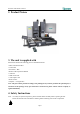
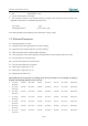
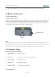
BGA2015 OPERATION MANUAL 2. Product Picture 3. The unit is supplied with Please check whether the following parts are included and intact. * Main Unit BGA EA-H15 * Control box * IR Camera—RPC * BGA EA-H15 Operation Manual * video line * USB connect line * video capture card * BGA tool box *computer、LCD(optional) Note: The parts will be packed according to the packing list. If you don’t purchase the optional part, it will not be in the package.
BGA2015 OPERATION MANUAL Note: Top and bottom IR radiator will be very hot during working, so explosive and combustible object or gas and solvent is strictly prohibited in working areas, also please don’ touch the hot housing parts Note: The laser alignment device includes a secondary laser device, so don’t see the laser bean directly.
BGA2015 OPERATION MANUAL 6.Movable Motor: stepping motor 7.Size 640*540*410(mm) 8.Camera output signal is video signal 9..The operation of Camera on PL and IR alternates according to the movement of PL’s telescopic arm. Brightness of IR camera is controlled by keyboard of PL. Net weight: Packaging dimension: 55kg 835*715*870(mm) Note: When purchasing the equipment, please indicate the working voltage. 5.
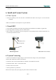
BGA2015 OPERATION MANUAL 7. T1=180℃ T0=185℃ S1=40s T2=185℃ S2=50s T3=228℃ S3=25s TL=217℃ TB=190℃ 6. Install and Connect System 6.1 Place System * Unwrap the packing of the unit, then take out BGAEA-H15 Main Unit and put it on the horizontal worktable. * Make sure whether the unit and parts are in good conditions. 6.2 Install RPC 1. Unscrew RPC Fixing Knob on the RPC Fixing Bracket and install RPC in the Bracket , tighten knob. 2. Put the plug of RPC connecting wire into Camera Socket. 3.
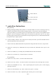
BGA2015 OPERATION MANUAL Connect USB line Connect video line Connect control box Connect ground line 7. control box Instructions IR system Key A. During selecting working flow period, UP and DOWN knob are used for controlling the moving upward or downward of cursor but when in standby interface, it can increase or decrease the digital.
BGA2015 OPERATION MANUAL L. Function of “YELLOW ” key: rotate it, adjust yellow light of camera; press it, close the light. 8. IR System Operation 8.1 Part Function * Adjust the Aperture System The Aperture System of Top Radiator can be adjust from 20×20 (mm) to 60×60 (mm) by two Adjustment Knobs. Unscrew the knobs before adjusting, and adjust the window size, then tighten knobs. The scale “2” on the housing means 20mm and “3’ means 30mm, other scale is similar.
BGA2015 OPERATION MANUAL The initial password of system is “000”. At the same time, system also has the omnipotent password “159”. If you forget the setting password, you can input “159” to make the password of system come back to initial password “000”. Note: If want to modify any parameter system, you must input password, otherwise, you can only browse them. For instance: Input the initial password “000” of system.
BGA2015 OPERATION MANUAL 2. 2.If you want to modify the next working flow, operate as the following B item; If you don’t want to modify, please press DOWN knob to browse the following parameter settings. B. Modify working flow For instance: Modify the working flow and make it become 1 flow. password: *** select: 0 password: *** select: 0 rotate MENU password: *** Step① select: 0 rotate MENU password: *** Step③ select: 1 Press MENU Step② Press OK Step④ password: *** select: 1 1.
BGA2015 OPERATION MANUAL select: 1 type: desolder After finishing modifying working mode, if you want to modify laser alignment mode, operate as D item shows; if no need to modify it, please press DOWN key to browse the next parameter settings. C-1. Modify Parameter of working flow 1. If it is necessary to modify parameter of a working flow, first you must select the working flow and then modify its parameter. The soldering technics is decided by T0, TB, T1, T2, T3, S1, S2 and S3.
BGA2015 OPERATION MANUAL TL Melting temperature of solder. At this temperature, the solder starts to melt down and turn into liquid. During the soldering and de-soldering, users can press CAL Key to calibrate the value of TL when the solder turn into liquid. In parameter modifying, use the UP and DOWN knob to set the value of TL. S1 Heating time rising from T1 to T2. User can set the value in the range of 0~300s. S2 Heating time rising from T2 to T3. User can set the value in the range of 0~300s.
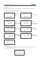
BGA2015 OPERATION MANUAL T1: 130℃ Press OK _T1: 130℃ S1: 060s T1: 130℃ S1: 060s Press MENU _S1: 060s T1: 130℃ rotate MENU T1: 130℃ rotate MENU Press MENU S1: 070s S1: 060s Press MENU rotate MENU T2: 150℃ S1: 060s Press OK T2: 160℃ T2: 160℃ Press OK T2: 150℃ T2: 150℃ S1: 060s Press MENU S1: 070s S1: 070s S1: 070s T1: 130℃ S1: 060s S1: 060s T1: 130℃ rotate MENU Press MENU T2: 160℃ Press MENU T2: 160℃ S2: 030s S2: 030s Page12 Press MENU
BGA2015 OPERATION MANUAL T2: 160℃ rotate MENU T2: 160℃ S2: 030s T2: 160℃ S2: 050s rotate MENU S2: 050s S2: 050s T3: 200℃ rotate MENU Press MENU TL: 183℃ rotate MENU TB: 140℃ Press MENU TL: 183℃ Press OK TB: 130℃ rotate MENU TB: 130℃ TB: 130℃ T0: 090℃ rotate MENU TB: 140℃ TB: 140℃ TL: 183℃ S3: 010s TL: 183℃ 按下 MENU TL: 183℃ rotate MENU T3: 200℃ S3: 010s TL: 183℃ Press OK rotate MENU T0: 090℃ rotate MENU T FAN:100S SPD: 80 T FAN:100S Page13 Press OK
BGA2015 OPERATION MANUAL TC:022˙C Tb:019˙C ready for flow D. Modify laser alignment mode For instance: Modify the laser alignment mode and set it to “on”. select: 1 rotate MENU type: desolder laser: off type: desolder type: desolder Press MENU rotate MENU type: desolder laser: off Press OK laser: on type: desolder laser: on 1. After finishing the modification, the next step communication speed, will not be able modified by keyboard. 2. Press OK key to exit.
BGA2015 OPERATION MANUAL If the bottom sensor is broken, it displays: TC: ***℃ B Tb: ***℃ sense error ! If above status happens, user should stop operating. 2. During the upward or downward movement of Top Heater or holding out and drawing back of fan arm, if it doesn’t reach over 10 seconds, the unit will come back to initial state all and singular in spite of what state it is here. It displays: TC: ***℃ Tb: ***℃ Move error ! 3.
BGA2015 OPERATION MANUAL 3. Adjust aperture system, and get a proper window size. 4. Adjust RPC in appropriate place, adjust size and focus of image with PL keyboard to display component image in the monitor clearly. 5. Select parameter with keyboard. (Refer to Parameters setting) A. Input password ”000” B. Select the required flow, if need to modify, perform relevant operation. C. Select “solder” working mode. D. Select “IR” laser alignment mode. E.
BGA2015 OPERATION MANUAL B. C. D. E. Select the required flow, if need to modify, perform relevant operation. Select “desolder” working mode. Select “IR” laser alignment mode. No change to communication speed, and press OK key to exit. IR window shows: TC:022˙C Tb:019˙C ready for flow F. Press START key and the system start working, perform content of selected flow. 7. After pressing START key, Bottom Heater starts to heat up and Top Heater moves downwards and reach to bottom. 8.
BGA2015 OPERATION MANUAL Micro-adjustment Knobs. Two PCB Fixing Knobs are used for locking PCB Clamp Bar to fix PCB. The other two Fixture Fixing Knobs are used for locking the PCB Fixture to prevent it from moving lengthways and transverse. The two Micro-adjustment Knobs are used for adjusting accurately while aligning the component. * Unscrew PCB Fixing Knobs and move the Slide Block to open the PCB Clamp Bar, make the distance in accordance with PCB size.
BGA2015 OPERATION MANUAL camera. When not in use, push it back, and the image displayed is got by IR camera. PL suck PL Camera 9.2 Aligning Technics 1. Place the soldered component in jig, move PCB Fixture to make the vacuum pen aim at component on the jig. Turn the Nozzle Controlling Knob to make nozzle move down to pick up component. The component should be picked up from its center. As soon as the vacuum nozzle touches component, the vacuum pump starts to work and pick up component.
BGA2015 OPERATION MANUAL superposing, please don’t do any change to the calibration plate or calibration tube. 5. Press UP key to make PL-HEAD move up. 6. Pull out PL Camera and adjust the image displayed by Keyboard. Observe the images: if the two images (Circle) in the Monitor superpose, the system is precise. If not, the system is imprecise, it needs to be adjusted.
BGA2015 OPERATION MANUAL vacuum suction nozzle and Top Heater to cool down. Take Suction Pad out of suction nozzle downwards, and install a new one in opposite direction. Note: PL EA-H15 is a precise equipment. Please don’t make any changes to it. Otherwise the precision of this equipment will be affected.
QUICK BGA EA-H15 OPERATION MANUAL 12、QUICKSOFT brief instruction 12.1 operation interface 1. Operation interface: this interface reaction executive condition of flow , we can real-time operate by this interface. 2. parameter of operation interface, be setting from “parameter testing interface”, in operation interface do not need setting. Parameter display K type sensor Flow curve display Have two technology mode, auto change from solder and desolder.
QUICK BGA EA-H15 OPERATION MANUAL close”,“cooling fan enter ” , “cooling fan out”. 12.2 counterpoint operation interface We can complete total counterpoint operation by counterpoint operation interface , contain focus, magnify reduce, suck component, etc. Counterpoint display Counterpoint working area status bar Up light close/up light open: click close or open top blue light. Down light close/down light open: click close or open top yellow light. Amplification: amplify picture of display window.
QUICK BGA EA-H15 OPERATION MANUAL Exit : exit “counterpoint operation ”interface, enter “operation interface”, current state have no change. When working area display aligning arm in ,then status bar location of aligning arm: external; When working area display vacuum open, then vacuum state in status : “close”. When status bar display “high speed mode”, express move speed is high, When status bar display “low speed mode”, express move speed is low. This function effect in counterpoint interface. 12.
QUICK BGA EA-H15 OPERATION MANUAL T0: only satisfy “TIR≥T0”, top infrared heater can start working. No special purpose, please set Tir> T0. Can also click “flow select” in “edit flow display”, call saved parameter and modify it. heat dissipation air quantity : 35~100. Note: parameter setting please refer to technology require. 12.4 curve analysis interface 1. 2. 3.
QUICK BGA EA-H15 OPERATION MANUAL Password setting: can set “enter password” and “parameter protect” two type password. The people who obtain enter password can operation this software, but no parameter modify power. The people who obtain parameter protect can operation this software, and modify parameter. If not set parameter protect password, people who obtain enter password also modify parameter. Language version select: can select language china or English.
Changzhou Quick Soldering Co., Ltd Add: No.11, FengXiang Road, Wujin High-Tech Industrial Development Zone, Jiangsu, China Tel: 86-519-86225678 Fax: 86-519-86558599 Zip code: 213167 Website: www.quick-global.