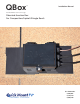
QBox ® Installation Manual Elevated Water Seal Technology® Patented Junction Box For Composition/Asphalt Shingle Roofs RESPECT THE ROOF U.S. Patent No.
Table of Contents Installation Instructions I. II. III. Important Safety Instructions………………………………1 I.I Save These Instructions……………………………...1 I.II Safety Callouts………………………………………..1 I.III Safety Warnings and Cautions………………………2 Product Description…………………………………………4 II.I Overview……………………………...……………….4 I.II Dimensions……………………………………………4 I.III QBox Contents………………………………………..5 Installation Overview………………………………………..6 II.I QBox Location…………………………………………6 IV. Installation…………………………………………………...7 IV.
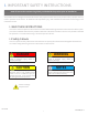
I. IMPORTANT SAFETY INSTRUCTIONS Read all instructions and warning labels provided with the product prior to installation. This product has been designed and tested to national safety requirements to ensure your personal safety. Improper use may result in potential electric shock. To reduce the risk of personal injury, read and follow all instructions and warnings in this installation manual. I.
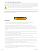
I.III Safety Warnings and Cautions This product is only to be installed by qualified personnel. These installation and service instructions are for qualified personnel only. To reduce the risk of electric shock, injury or death, all wiring and connection must be performed by qualified personnel. Do not perform any installation or service other than that to which you are qualified to perform. Lethal voltages are present during the installation, operation and service of this equipment.
• If any part of this product becomes damaged, remove and discard the entire unit, and replace with a new one. Failure to do so could result in fire, property damage, personal injury, electrocution, or death. • When disconnecting the inverter, allow 15 minutes for all electrical storage components to discharge before servicing any conductors in that circuit. • Do not install this equipment in wet conditions. This could result in electrocution, personal injury, or death.
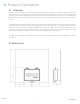
II. Product Description II.I Overview The QBox Junction Box sits on top of a durable anodized aluminum flashing which utilizes Quick Mount PV’s patented Elevated Water Seal Technology® to waterproof the fasteners that connect the QBox to the roof. The QBox is designed to secure to the roof’s sheathing without a pilot hole for fast installation and optimal roof placement.
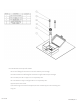
Not Included Due to Site Specific Needs: • Strain relief fittings for PV homerun wires for sidewall pass-through. • Conduit connectors and fittings for transition wiring for sidewall pass-through. • #8 - #12 AWG, min 90° C copper wire as required by NEC. • #6 - #10 AWG bare copper roof ground wire as required by NEC. • Approved wire connectors. • 3/4" EMT fitting to transition from QBox 3/4" EMT conduit nipple to attic building wire. • Lug nut. BI 7.2.
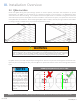
III. Installation Overview III.I QBox Location Locate the QBox during the system design process to ensure optimal placement and compliance to permit requirements. The QBox can be installed at any convenient location on the roof since it is designed for direct securement to the roof’s sheathing. It is acceptable to install the QBox under a PV module as long as the maximum rated ambient temperature of the QBox will not be exceeded.
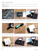
IV. Installation Tool Specs: Shingle ripper bar, lumber crayon, 1" spade pit, hand broom, caulk gun, appropriate sealant, 1/2" nut driver, #3 phillips screw driver. Side Mount Conduit Exit: For side mount conduit exit, where transition wires leave the QBox from the side of the box, skip steps 3-5 and 8-10. 2 1 Remove Nails: Use roofing bar to break seals between 1st and 2nd and 3rd shingle courses. Be sure to remove any obstructing nails to allow correct placement of the QBox.
12 10 Finish Conduit Attach: Hand tighten threaded conduit cap to secure conduit nipple in place. This will hold the QBox flashing in place when securing it to the roof. 11 Secure to Roof: Screw the anchor bolts with sealing washers through the mounting holes and into the roof sheathing securing the QBox to the roof. No pilot hole is required. Close Lid: Close and thread the bolt into the nut by hand. Then using a #3 Philips drive, turn bolt until the top and bottom tabs securing the bolt are flush. V.
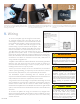
Transition to building wiring: If you are using the attic exit, several inches of 3/4" EMT QBox conduit nipple will be visible in the attic. A number of options exist to transition from the 3/4" EMT QBox conduit nipple to the building wiring. By using a 3/4" EMT to Rigid threaded coupler, as well as a 3/4" to 1/2" threaded reducer, many standard 3/4" and 1/2" knockout fittings can be be utilized to transition to NM, MC, Flex, etc. The following are some possible configurations.
Tool Specs: Appropriate weather tight conduit fittings and cord grips, hole saw, adjustable crescent wrench, wire strippers and cutters. Configurations Shown: The following installation steps are for a single string transition using cord grips for the home run cables from the PV system. There are two ways to transition wiring from the QBox. The first is through the attic using the QBox’s pre-installed, conduit pass-through with the patented Elevated Water Seal Technology® (steps 4-6).
VI. Wiring Diagrams and Proper Use The QBox can be used to transition a single string, two parallel strings, or two combined strings. Below are wiring diagrams for all the approved use cases. All wires are to be copper conductors with insulation rated to 90°C or higher. Maximum size of incoming PV string wires is #10 AWG. Maximum size of outgoing branch circuit is #8 AWG. Ground wires can be green or bare according to the NEC.
Two Combined Strings WARNING KING INNOVATION WIRE CONNECTORS ALLOWABLE WIRE SIZES UL Standard 486D DryConn® Aqua/Red DryConn® Aqua/Blue 1 #8 w/ 1 #12 1 #6 w/ 1 #12 2 or 3 #10 1 #8 w/ 1 #10 1 #10 w/ 1 or 2 #12 1 #8 w/ 1 or 2 #12 2 #10 w/ 1 #12 1 #8 w/ 1 #10 w/ 1 #12 2 or 3 #12 2 or 3 #10 Before wiring of the QBox, ensure all cables are de-energized. Do not work with energized electrical cables. Energized electrical cables are a shock hazard.
Building wiring strapping: Per the NEC, wire or conduit must be secured within 12" of leaving the QBox conduit nipple. (EMT can be 3') Exterior Conduit Drop: The QBox can be used to transition to a conduit drop on the exterior of the building. Blocking must first be installed to the roof overhang below the location where the QBox will be mounted. The QBox conduit nipple will pass through both the roof and blocking and the QBox lag bolts will secure into the blocking.
VII. System Specifications and Ratings QBox Specifications: • Maximum Voltage: 600 Volts • Maximum Current: 40 Amps • Allowable Number of Strings: 2 • Allowable Wire: »» Inputs: 12 AWG - 10AWG »» Outputs: 12AWG - 8AWG »» Ground: 12AWG - 6AWG • Enclosure Rating: Type 3R • Roof Slope Range: 2.5:12 - 12:12 • Attic Conduit Pass-Through: ¾" EMT • Max Side Wall Conduit Size: ¾" • Dimensions: »» Box: 5.76" W x 5.4"D x 2.
RESPECT THE ROOF 925-478-8269 | 2700 Mitchell Dr. | Walnut Creek, CA 94598 www.quickmountpv.com | tech@quickmountpv.com BI 7.2.3-44 ©2017 by Quick Mount PV. All rights reserved.