
2020 Installation Guide


BI 7.2.3-46
Feb-2021, Rev 14
BI 7.2.3-46
Feb-2021, Rev 14
20
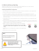
INCORRECT CORRECT
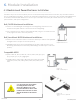
Optional gauge fabrication:
•
Fabricate an installation jig shown in image 5.3.3
Installing Shared QRail Configuration
Image 5.3.3
Shared rail distance gauge
Image 5.3.4
Image 5.3.5
Array Installation:
•
Aer determining the location of the array on the roof, mark the location of the lower rail with a chalk line or other suitable
method.
•
Determine the raer locations and mark them on the E-W chalk lines.
•
Install the roof attachments along the chalk line per the manufacturers’ instructions taking care to align the L-foot
mounting point (mount bolt) as closely as possible to the intersection of the raer and the chalk line, accounting for
oset of the L-feet. Mounts that are adjustable in the N-S position, such as the Quick Mount PV Shared Rail Composition
Mount are recommended.
•
Install and tighten the L-feet on the two end mounting/ flashings taking care to place the upright stays of the L-feet as
closely aligned with the marked line as possible with the faces of the stays as closely parallel to the line as possible.
•
Stretch a reference string between the end L-feet and attach the remaining
L-feet with the upright stays just touching the reference string and secure
them in position.
•
Using the gauge fabricated earlier or using a measuring tape or other suitable
method, locate and mark the positions of the remaining rows of the array.
•
Install the remaining mounting/ flashings and L-feet and check frequently to
ensure proper N-S spacing of the upright surfaces of the L-feet stays within
the distance gauge.
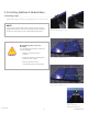
•
Position the rail in place E-W and hold each end of the rail against the end
L-feet. Insert the pre-assembled T-head rail fasteners in the end L-feet into
the slot on the side of the QRail rail. Using a spirit level or other suitable
device, set and hold the rail level at the desired height by moving the
T-head bolt up or down in the L-foot. See Image 5.3.4.
•
Using a " or 13mm socket, tighten the rail fastener nuts to 192 in-lbs (22
N-m). (Be sure to allow the bolt head to rotate as far as possible in the
T-head channel to ensure full engagement of the bolt head with the sides
of the channel). Full engagement is confirmed when the alignment
line on the end of the T-bolt is vertical. See Image 5.3.5.
•
With each end of the rail secured and the rail level, proceed along the line of
L-feet, inserting the T-head bolts into the rail side channel and tightening as
above.
Rail Spacing = module - in