
2020 Installation Guide


BI 7.2.3-46
Feb-2021, Rev 14
BI 7.2.3-46
Feb-2021, Rev 14
12
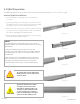
Image 2.5.3
Lug installed in side channel
Image 2.5.4
Lug installed in top channel
AWG Wire Size QMR-GLQ-A-50 Capacity
12 - 6 1 wire
10 2 wires
12 2 wires
Table 2.5.1
Grounding Lug wire capacity
The QMR-GLQ-A-50 Grounding Lug is preassembled with a M8-T-bolt,
serrated flange nut, and a wire capture bolt. The lug can be installed
in the top or side channel of the QRail rail in any orientation.
•
Insert T-head bolt head into the rail’s top or side channel. Be sure
to allow the bolt head to rotate as far as possible in the T-bolt
channel to ensure full engagement of the bolt head with the sides
of the channel.
•
Tighten M8 nut to [192 -lbs (22 N-m)]
Using the above procedure, install a QMR-GLQ-A-50 Grounding Lug
on each segment of the array. Once all the QMR-GLQ-A-50 Grounding
Lug are installed, use a continuous length of wire to connect each rail
by laying wire in the lug wire channel and secure with the wire capture
bolt. Torque to 60in-lbs (7N-m) for a 6-8 AWG wire or 36in-lbs (4N-m)
for a 10-12 AWG wire.
QMR-GLQ-A-50 Grounding Lug Installation
The bonded array segments must be connected to the system ground electrode using
a single continuous copper wire. This is achieved by routing the grounding cable
through the QMR-GLQ-A-50 Grounding Lugs on each array segment. (Image 2.5.3 and
2.5.4)
Array Grounding
ATTENTION
Caution
When dissimilar metals come into contact, it is possible
that they will react with each other and cause corrosion
in one or both of the metal surfaces. Aluminum and
copper are particularly reactive with each other;
care must be taken to prevent any contact between
aluminum components and bare copper wire (Image
2.5.3 and 2.5.4).
Place QMR-GLQ-A-50 grounding lug in a location on the
top of the rail that reduces the risk of contact with the
module backsheet under load. Side channel installs may
also be used to further reduce risk.
Galvanic Reaction