
How to Guide


10
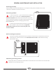
Lay a carpenters square on the floor against the inner surface of the guide bar and mark a vertical and horizontal line; this
becomes the center of each bored hole.
BORING THE HOLES FOR THE BASE
BORING THE HOLES FOR THE BASE
DOOR STOP
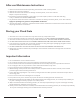
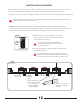
An engineer will advise on the most appropriate method of boring the hole. Two popular methods include (but are not
limited to) the use of a high pressure water saw or a diamond faced concrete hole drill.
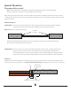
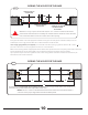
Use a straight, rigid guide bar (not supplied), cut to the width of the door opening. A guide bar made of 1
¼
” x 1
¼
” x 1/8”
(31.75 mm x 31.75 mm x 3.17 mm) angle steel or aluminum is recommended.
Mark a line across the guide bar at appropriate intervals. These marks represent the center line spacing of the holes to be bored.
The intervals depend on the mix of Floodgate units you identified at the planning stage as the most suitable.
ILL I
90º
SHIMS OR CLAMPS
ON BOTH ENDS
AS SHOWN
STRAIGHT RIDGED
GUIDE BAR
3”
CENTER LINE OF
STANCHION
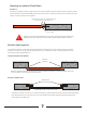
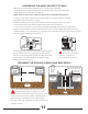
Whether or not you opt to use the side rails, the 3 in. / 76.2 mm centerline dimension
of the bored stanchion holes must always be maintained from whatever surface the back
face of the Flood Gate comes into contact with on the opening.
CAUTION:
BB BB B
3” 3”
8”
A
This illustration is an Example of an opening of 14¼ ft for (A). Using 5 Flood Gates, each stanchion, or
dimension (B) is positioned at their respective center lines.
NOTE: The 3 in. / 76.2 mm set back dimension to the center line of the bored holes is
critical to insure proper alignment of the Flood Gate panels.
ILL J