Q-Tech Q-Tech Commercial Series QTA 6060M/6120M/6250M Mixer Amplifiers User Manual
Contents Safety Precautions . . . . . . . . . . . . . . . . . . . . . . . . . . . . 1 General Description. . . . . . . . . . . . . . . . . . . . . . . . . . . . 4 Features. . . . . . . . . . . . . . . . . . . . . . . . . . . . . . . . . . . . . 4 Front Panel Layout. . . . . . . . . . . . . . . . . . . . . . . . . . . . . 5 Rear Panel Layout . . . . . . . . . . . . . . . . . . . . . . . . . . .
QTA 6000 Series User Manual Safety Precautions • Be sure to read the instructions in this section carefully before use. • Make sure you observe the instructions in this manual as the conventions of safety symbols and messages are very important. • We also recommend you keep this instruction manual handy for future reference. Safety Symbol and Message Conventions Safety symbols described below are used in this manual to prevent bodily injury and property damage which could result from mishandling.
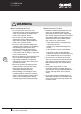
QTA 6000 Series User Manual WARNING When Installing the Unit • Do not expose the unit to rain or an environment where it may be splashed by water or other liquids, as doing so may result in fire or electric shock. • Use the unit only with the voltage specified on the unit. Using a voltage higher than that which is specified may result in fire or electric shock. • Do not cut, kink, otherwise damage nor modify the power supply cord.
QTA 6000 Series User Manual CAUTION When Installing the Unit • Never plug in nor remove the power supply plug with wet hands, as doing so may cause electric shock. • When unplugging the power supply cord, be sure to grasp the power supply plug; never pull on the cord itself. Operating the unit with a damaged power supply cord may cause a fire or electric shock. • When moving the unit, be sure to remove its power supply cord from the wall outlet.
QTA 6000 Series User Manual General Description The 7 input channel mixer amplifier is designed for distributed paging and background music systems and in applications where music on hold (MOH) plus paging is required. With 5 microphone/line inputs and 1 stereo input, the series mixer amplifiers will accommodate a variety of input sources including paging microphones, CD players, and digital music players.
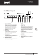
QTA 6000 Series User Manual Front Panel Layout 1 1. Input 1-7 Controls The gain for input channels 1-7 are controlled by these rotary controls. The MASTER GAIN CONTROL must be turned up in addition to the input controls for audio to be present at the speaker terminals. Input 7 may be used as a dedicated input for paging via the PABX. 2. Tel Input Telephone input volume control 3.
QTA 6000 Series User Manual Rear Panel Layout 32 31 11 30 29 28 12 27 26 13 14 15 11. Power Socket 6 Connect the power cord to 240VAC only. Serious damage may result if accidentally connected to other line voltages. 12. Pre Out The PRE OUT connector has Post tone control signals available to drive another power amp or external audio devices.
QTA 6000 Series User Manual 17. Input 7 if used for Phone Paging 22. Dipswitch “A” Positions 1-6 Tel inputs are balanced, line or mic level (Refer to Dipswitch Bank 1-8 for setting input sensitivity). Or wiring unbalanced inputs, tie (short) the (G) and (-) terminals together. Understanding the functionality of the dipswitches is key to getting the most out of the 60w/120w/250w mixer amps. Whether the switch is in the “Up” or “Down” position is critical to the function of the amplifier. 18.
QTA 6000 Series User Manual 23. Dipswitch “B” Positions 1-8 1 2 3 4 5 6 25. VCA 7 8 Input 6 Input 5 Input 4 Input 3 Input 2 Input 1 Phantom VCA Sens 100mV Line Line Line Line Line off Master 300mV Mic Mic Mic Mic Mic on Input 6 8 Dipswitch 1 When set to the “100mV” position, the sensitivity of Input 6 is suitable for inputting Telephone Paging Signals. When set to the “300mV”position, the sensitivity of Input 6 is suitable for CD/DVD player outputs.
QTA 6000 Series User Manual 29. Bridge Select 31. SPEAKER TERMINALS The “Bridge Select (Sel)” terminals are the access point to activate the “Bridge In / Out” feature. To activate the feature connect the two points together via an external contact closure. These two points must be connected to send or receive any signal. By connecting the Bridge In / Out terminals of the Mixer amp, a simple room combining system can be accomplished.
QTA 6000 Series User Manual Connections Speaker Connections COM 4 70V 100V COM 4 70V 100V COM 40.8 70V 100V 83 (QTA 6120M) 100V LINE 70V LINE 4 4 (QTA 6120M) Notes: • Both the 4Ω 70V/100V terminals cannot be used at the same time • Impedances indicated in the figures represent the total speaker system (load) impedances WARNING 10 Be sure to attach the supplied terminal cover after connection completion.
QTA 6000 Series User Manual Applications Quick Start Examples Example 1 System Paging, BGM, and MOH with Remote Master Level Control. This application has the paging microphone into INPUT 1, BGM (CD player) into Input 2, and a Message Repeater or MOH into Input 6. The Zone 2 Output is sent to the telephone system’s MOH input port. A level control may be placed in another area such as a front desk to adjust the system’s level without having to go the equipment room.
QTA 6000 Series User Manual Example 2 - Hotel Room Combining Using Two QTA 6000 Series This example utilizes the combining feature of the Quest mixer amplifiers. The drawing below shows the equipment connections for two hotel ballrooms, separated by an operable wall. The hotel needs to be able to have the audio system operate as one large unit (wall open) or two discreet systems (wall closed).
QTA 6000 Series User Manual Example 3 - Small House of Worship The diagram below shows a typical small House of Worship audio system. This system utilizes four microphones, one for the Pulpit and three on the choir. A Master volume control (Quest VC - 10K) is connected to the “VCA” terminals for overall level control. For background music, a CD player’s audio outputs are connected to Input 6, and a recording device (cassette recorder or computer’s audio input) is connected to the Tape Out jacks.
QTA 6000 Series User Manual Block Diagram 14 User Manual Q-Tech Commercial Series QTA 6060M/6120M/6250M
QTA 6000 Series User Manual Specifications Mixer Amplifier Type Mixer Amplifier Model QTA-6060M Rated Output Power 60W QTA-6120M QTA-6250M 120W 250W Transformer Outputs 4Ω,70V/100V Frequency Response 50Hz~16KHz±2dB Distortion <1% at rated power (1KHz) Input 1 : Line/Tel 316mV(-10dBV) 10Kohm (600Ωw optional/ transformer) Sensitivity Mic :316mV~3.16mV (-50dBV~-70dBV) Input 1-5 : Line 316mV(-10dBV) 10Kohm Mic 316mV~3.
QTA 6000 Series User Manual Dimensional Diagram UNIT: mm 16 Keep all the unit’s sides over 10cm away from objects that may obstruct air flow to prevent the unit’s internal temperature rising.
QTA 6000 Series User Manual Technical Notes voltage outputs (70V 100V) and a terminal at one end for the negative return wire (COM). Constant Voltage Distributed Speaker Systems Demystified In a typical paging and background music speaker installation, quantity loudspeakers are placed across a single amplifier in a parallel wiring configuration (see Fig 1.).
QTA 6000 Series User Manual 15% discrepancy can mean that a 100 watt system will only be able to power 7 or 8 x10 watt speakers safely. Be aware of this booby trap. Always plan to have 20% more power than you think you will need. 2. Incorrect output connection: If you accidentally connect your terminal strip on the amplifier to the 8 ohm output instead of the 100/70V line, you will have distortion and risk damaging the amplifier.. 3.
QTA 6000 Series User Manual High impedance of speakers and output calculation table for 100Volt systems Output 0.1W 0.5W 1W 2W 3W 5W Impedance 100KΩ 20KΩ 10KΩ 5KΩ 3.33KΩ 2KΩ Output 10W 15W 20W 25W 30W 35W Impedance 1KΩ 667Ω 500Ω 400Ω 333Ω 286Ω Output 40W 50W 75W 100W 150W 200W Impedance 250Ω 200Ω 133Ω 100Ω 66.
QTA 6000 Series User Manual 20 User Manual Q-Tech Commercial Series QTA 6060M/6120M/6250M
www.questaudio.net Quest Engineering Pty Ltd 86 Derby St.