Q-Tech Q-Tech Commercial Series QTA 1360P/1480P Power Amplifiers User Manual
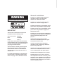
WARNING THIS APPLIANCE MUST BE EARTHED General Installation DO NOT run unbalanced high impedance microphone cables near mains, data, telephone or 70/100V line cables. DO NOT run 70/100V line cable near data, telephone or other low voltage cables. DO NOT exceed 90% of the amplifiers output power when using 70/100V line (speech only). DO NOT exceed 70% of the amplifiers output power when using 70/100V line (high level background music).
QTA 1360P/1480P User Manual Contents Introduction. . . . . . . . . . . . . . . . . . . . . . . . . . . . . . . . . . 2 Description . . . . . . . . . . . . . . . . . . . . . . . . . . . . . . . . . . 2 Front Panel Layout. . . . . . . . . . . . . . . . . . . . . . . . . . . . . 3 Rear Panel Layout. . . . . . . . . . . . . . . . . . . . . . . . . . . . . 3 Power Source . . . . . . . . . . . . . . . . . .
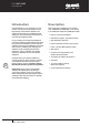
QTA 1360P/1480P User Manual Introduction Description Congratulations on your purchase of a new Q-Tech Commercial series amplifier. Quest Engineering Q-Tech Series amplifiers are engineered and built to a standard that will satisfy the most demanding environments of commercial installation audio. QTA series power amplifiers cover models from 120W RMS to 480W RMS. This manual is for 360W QTA 1360P and 480W QTA 1480P.
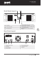
QTA 1360P/1480P User Manual Front Panel Layout 1 5 6 4 2 3 1 Power Switch 4 Protection indicator LED - lit when overheating, short circuiting and overloading 2 Channel volume control 5 Peak indicator LED - lit when max wattage output and output signal distortion 3 Power indicator LED 6 Signal indicator LED - lit when input signal is detected 3 Rear Panel Layout 1 2 3 4 5 6 1 Speaker Output Terminal 4 DC Power Supply Terminal 2 2/XLR Input 6 AC Power Input Socket 3 Phone J
QTA 1360P/1480P User Manual Power Source AC Power Source The supply transformer has been designed for AC 240V /115V (±10%) 50 /60 Hz. DC Power Source Battery Connection (24Vdc) When using external batteries, please ensure the amplifier is grounded via the screw terminal. (Electrical stability of the system will be improved by providing a good earth ground.) When connecting batteries, please ensure correct polarity. Speaker Output Connection The speaker output screw terminal is on the rear panel.
QTA 1360P/1480P User Manual Installation Practice Step 1. Take a piece of figure-8 cable, connect the stripe/coloured wire to the 100V terminal and the uncoloured wire to the COM on the amplifier terminal strip. Step 2. Connect the other end of the wire (uncoloured) to the Com/EARTH connection on the ceiling speaker transformer and the other + (strip) wire to the required voltage taping. Step 3.
QTA 1360P/1480P User Manual Trouble Shooting If the amplifier fails to work as required, please check the following: No Power, No Lights • Make sure amplifier power switch is on. • Make sure mains power switch is on at the wall. • Check the mains and DC fuse. • Replace with only the correct type and rating. Distorted Output • Check that the speaker type is correct for the output that you are using (ie. 4-16Ω, or 100V line). • Check for any short circuits on the speaker line.
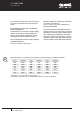
QTA 1360P/1480P User Manual Technical Notes Constant Voltage Distributed Speaker Systems Demystified In a typical paging and background music speaker installation, quantity loudspeakers are placed across a single amplifier in a parallel wiring configuration (see Fig. 1). Each ceiling speaker will contain a small transformer and you will notice that the connection block near the transformer will have a common terminal (C or earth), and a number of wattage terminals.
QTA 1360P/1480P User Manual For the benefit of those who want to calculate the power of the system with a formula. See below: Determining power by calculating total impedance The alternative to counting the speaker taping watts is to calculate the total impedance of the line, which will also indicate the wattage necessary to drive the system correctly.
www.questaudio.net Quest Engineering Pty Ltd 86 Derby St.