
User manual
INSTALLATION
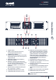
OUTPUT ASSIGNMENT
PIN 1+ :
PIN 1- :
SIGNAL
GROUND
LIN K A
LIN K B
INP UT A
IN
PUT B
Push To Reset
~
220 240V 10A 50 /60H z
OUTP UT A
OUTP UT B
BR
IDGE
PIN1 :
PIN2 :
PIN3 :
SIG
NAL
GND
SIGN AL
+
SIGN AL
-
CAUTION
RISK OF ELECTRIC SHOCK
DO NOT OPEN
OFF 80 Hz 11 0Hz
LOW PASS -A
OFF 35Hz 80Hz
HIGH PASS -A
26dB
32dB1.4V
GAIN
STEREO PARALLEL BRIDGE
MODE
STEREO
MOD E
OFF 35Hz 80Hz
HIGH PASS -B
OFF 80 Hz 110 Hz
LOW PASS -B
ON OFF
LIMITE R
LIFT GROUND
GROUND
DESIGN ED BY QUE ST ENGI NEERING ,AUSTRA LIA
MODEL:
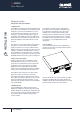
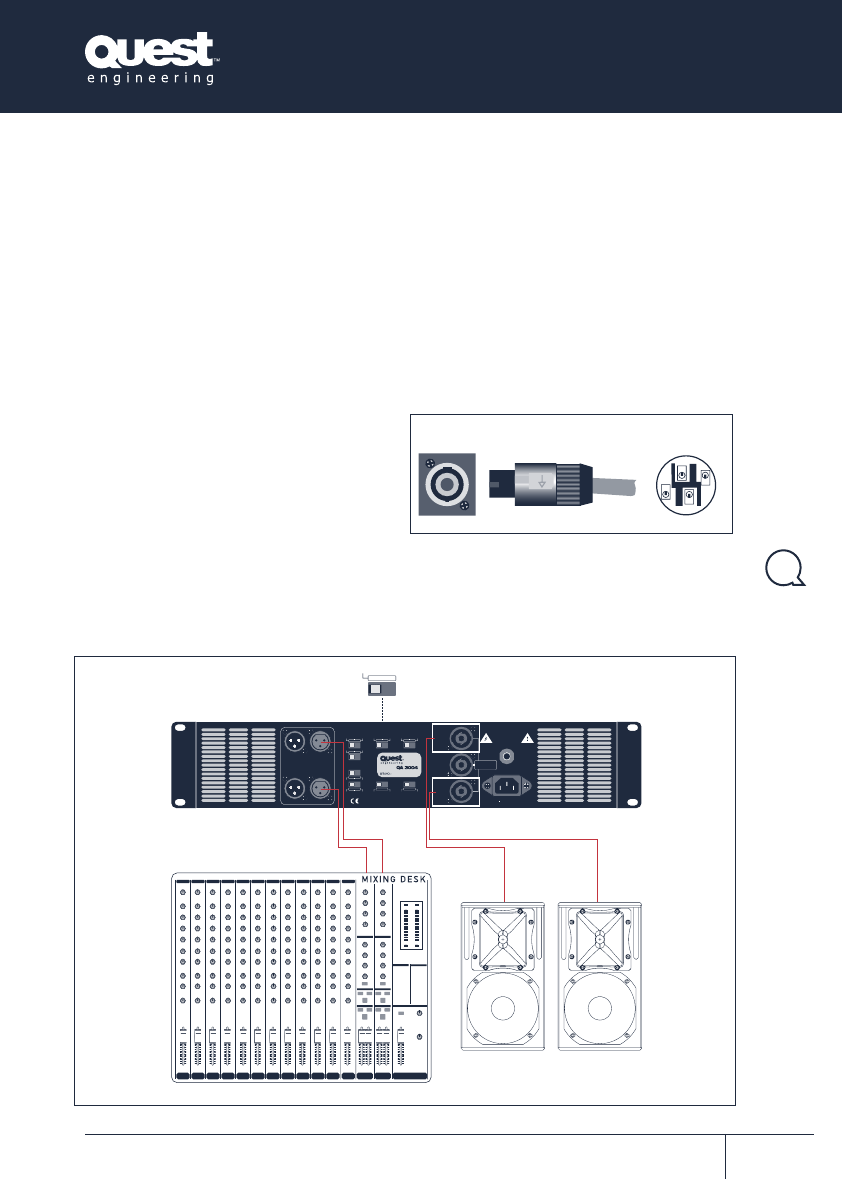
Stereo Operation
System configuration diagrams
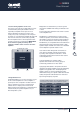
each other. The A channel handles the positive voltage
swing and the B channel becomes the negative, thus
doubling the output voltage swing. Via the “bridge
output” speaker connector, the speaker is now
connected across the two channels.
Power is proportional to the square of the voltage
swing, so four times the output power is possible. The
reality is that this would exceed the capability of the
output stage but a considerable increase in output will
result all the same.
C
aution : In this mode output voltages are high
enough to constitute a shock hazard.
Wiring will need to conform to CLASS 1 wiring
standards. Check your local electrical codes for the
appropriate electrical standards.
Output is via the middle Speakon connector. The
output signal is across pins number 1+,1-.
ALWAYS SWITCH OFF AMPLIFIER BEFORE
OPERATING BRIDGE SWITCH
The minimum load impedance in bridge mono
mode is 8Ω
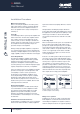
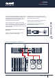
2+
2-
1+
1-
3. SPEAKON CONNECTOR WIRING
3. Speakon input and output connector wiring.
QA SERIES
User Manual
User Manual
QA Series
Power Amplifiers
9