
User manual
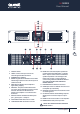
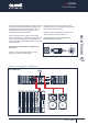
CONNECTIONS
1. ON/OFF Switch.
2. LEVEL Control of the input level of the
external signal in 3dB increments.
3. POWER Status available.
4. SIGNAL Signal status indicators: These LEDs
indicate signal presence for both the inputs of
channel A and B.
5. PEAK Status indicates when amplifier is
approaching clipping.
6. PROTECT The protect LED indicates that
one of the various amplifier protection circuits
has been activated.*If LED remains on
please return amplifier to a certified service
technician.
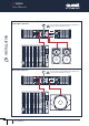
7. INPUTS Channel A/B balanced XLR inputs:
pin 1 ground, pin 2 + and pin 3 -
8. HIGH PASS FILTER Selectors for A & B.
9. LOW PASS FILTER Seclectors for A & B.
10
. MODE This switches amplifier operational
mode from Stereo/Parallel Mono or Bridge
Mono. Input is across channel A. Minimum
speaker impedance is 8Ω in bridge mode.
Please refer to page 7 of this manual for
correct wiring instructions. AWLA YS SWITCH
OFF AMPLIFIER BEFORE OPERATING
BRIDGE SWITCH.
11. LIMITER Switches between off and on.
12. GAIN Input switch to calibrate mixer line level
to amplifier input sensitivity.
13. GROUND Seperates electrical earth from that
of chassis ground.
14. OUTPUTS Channel A/B and Bridge Outputs.
Speakon NL4 connectors output on pin1+
and 1-
15. RESET Push circuit breaker to reset amplifier.
16. MAINS INPUT Mai
n power input IEC.
SWITCH OFF AMPLIFIER BEFORE OPERATING
BRIDGE SWITCH
’
(
)
*
+
,
OUTPUT ASSIGNMENT
PIN 1 + :
PIN 1 - :
SIGN AL
GR
OUND
LIN K A
LIN K B
INP UT A
IN
PUT B
Pus h To Reset
~
220 240 V 10A 5 0/60 Hz
OUT PUT A
OUT PUT B
BRI DGE
PIN 1:
PIN 2:
PIN 3:
SIG NAL GN D
SIG NAL +
S
IGN AL -
CAUTION
RISK OF ELECTRIC SHOCK
DO NOT OPEN
OFF 80Hz 110Hz
LOW PAS
S -A
OFF 35H z 80Hz
HIGH PASS -A
26dB
32dB1.4V
GAIN
STEREO PARALLEL BRIDGE
MODE
OFF 35H z 80Hz
HIGH PASS -B
OFF 80Hz 1 10Hz
LOW PAS
S -B
ON OFF
LIMIT ER
LIFT GROUN D
GROUND
DESIG NED BY Q UEST ENG INEERIN G,AUST RALIA
N238 8
MODEL:
- .
/ Ll Ln
Lk Lm Lo Lp
Lq
QA SERIES
User Manual
QA Series
Power Amplifiers
User Manual
5