
User manual

HPI212S
User Manual
User Manual HPI Series
HPI212S
4
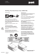
Connections
Two NL-4 connectors are mounted in a
recessed panel on the rear surface of the
box. This allows the speaker box to be set flat
against a wall without physical interference to
the speaker connector.
• The connector input is wired pin 1+ and
pin 1-.
• Pin 2 is not connected.
Take care when inserting the Speakon
connector twisting the connector until it
locks into place. Reverse the procedure to
disconnect.
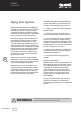
Getting The Best From Your HPI212S
Amplification
The performance of any loudspeaker depends
on the amplifier delivering an adequate
supply of clean power.
Please ensure a suitable amplifier is selected
for use in conjunction with the HPI212S and
accompanying speaker system.
Power in the Right Hands Can Save
Your Speakers
If the loudspeakers are used for a
professional application with competent
operators, the power principle is as follows:
When the loudspeaker is needed to achieve
maximum output levels, the amplifier
should be able to sustain a peak of twice
the wattage listed in the loudspeaker
specifications. A quality amplifier will provide
a clean peak voltage capability of 6 dB above
the maximum RMS power of the amplifier.
To avoid “clipping” or distorted output
from a lesser quality amplifier, select an
amplifier with double the RMS power rating
of the loudspeaker. The thermal limits of the
speaker are unlikely to be exceeded with an
undistorted signal.
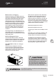
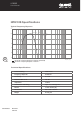
HPI212S in Recommended
Configuration (4 ohm)
Reducing low frequency output below 35 Hz
will make more amplifier power available for the
audible bass frequencies and help to prevent the 12”
drivers from excessively heating up.
OUTPUT ASSIGNMENT
PIN 1+ :
PIN 1- :
SIGNAL
GROUND
LINK A
LINK B
INPUT A
INPU T B
Push To Reset
~
220240V 10A 50/60Hz
OUTPUT A
OUTPUT B
BR
IDGE
PIN1:
PIN2:
PIN3:
SIGNAL GND
SIGNAL +
SIGNAL -
CAUTION
RISK OF ELECTRIC SHOCK
DO NOT OPEN
OFF80Hz110Hz
LOW PASS -A
26dB
32dB1.4V
GAIN
STEREO PARALLEL BRIDGE
MODE
OFF35Hz80Hz
HIGH PASS -B
OFF80Hz110Hz
LOW PASS -B
ON OFF
LIMITER
LIFTGROUND
GROUND
DESIGNED BY QUEST ENGINEERING,AUSTRALIA
MODEL:
OFF35Hz80Hz
HIGH PASS -A
OFF 35Hz80Hz
HIGH PASS -A
10
1
12
5
10
1
5