
Technical data


124 • BACnet/IP Controller 750-830
LED Signaling
WAGO-I/O-SYSTEM 750
BACnet/IP Controller
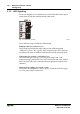
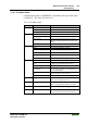
3.1.9 LED Signaling
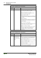
For on-site diagnostics, the controller has several LEDs that indicate opera-
tional status for both the controller and the entire node.
24V 0V
++
01
02
ETHERNET
C
D
B
A
C
B
A
24V 0V
++
01
02
C
D
B
A
C
B
A
LNK
ACT
BT
MS
I/O
BACnet/IP
NS
USR
A
B
Fig. 3-14:Indicators 750-830 g083002x
Three different groups of LEDs are differentiated.
Fieldbus status (see section 3.1.9.1)
This LED group includes the single and two-color LEDs designated
"LINK/ACT (green), "BT" (green), "MS" (red/green) und "NS" (red/green)
that indicate the status of fieldbus communication and the operating mode.
Node status (see sections 3.1.9.2 and 3.1.9.3)
The LEDs arranged at the type "I/O" (red/green/orange) and "USR"
(red/green/orange) indicate the status of the internal bus and of the fieldbus
node. The USR LED can be controlled from an application program in the
controller.
Status of power supply (see section
3.1.9.4)
The LEDs A and B signal 24 V power supply (A) and the field side supply,
i.e. to the power jumper contacts (B).