Modular I/O System BACnet/IP Controller 750-830 Manual Technical description, installation and configuration Version 1.0.
• General Copyright © 2008 by WAGO Kontakttechnik GmbH & Co. KG All rights reserved. The contents of this documentation are taken in part from the BACnet Standard 135-2004 or are based on the original contents. These contents are subject to copyright. The following applies to these contents: ©2004, American Society of Heating, Refrigerating and Air-Conditioning Engineers, Inc. (www.ashrae.org). Reprinted by permission from 2004 ASHRAE Standard-135.
Content • 3 Content 1 Important Notes .......................................................................................... 6 1.1 Legal Principles........................................................................................ 6 1.2 Standards and Regulations for Operating the 750 Series ......................... 8 1.3 Symbols .................................................................................................... 9 1.4 Safety Information............................................
• Content 6.12 6.13 6.14 6.15 6.16 6.17 6.18 6.19 6.20 6.21 6.22 6.23 6.24 6.25 6.26 6.27 6.28 6.29 6.30 6.31 6.32 6.33 6.34 6.35 6.36 6.37 6.38 6.39 6.40 6.41 6.42 6.43 6.44 6.45 6.46 6.47 6.48 6.49 6.50 6.51 6.52 6.53 6.54 6.55 6.56 6.57 6.58 6.59 Configuration_Files.............................................................................. 282 COV_Increment ................................................................................... 282 Database_Revision ....................................
Content 6.60 6.61 6.62 6.63 6.64 6.65 6.66 6.67 6.68 6.69 6.70 6.71 6.72 6.73 6.74 6.75 6.76 6.77 6.78 6.79 6.80 6.81 6.82 • 5 Priority_For_Writing............................................................................ 302 Protocol_Object_Types_Supported...................................................... 302 Protocol_Revision ................................................................................ 303 Protocol_Services_Supported ............................................................
• Important Notes Legal Principles 1 Important Notes This section provides only a summary of the most important safety requirements and notes which will be mentioned in the individual sections. To protect your health and prevent damage to the devices, it is essential to read and carefully follow the safety guidelines. 1.1 Legal Principles 1.1.1 Copyright This manual including all figures and illustrations contained therein is subject to copyright.
Important Notes Legal Principles • 7 All personnel must be familiar with the applicable standards. WAGO Kontakttechnik GmbH & Co. KG declines any liability resulting from improper action and damage to WAGO products and third party products due to non-observance of the information contained in this manual. 1.1.
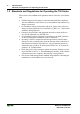
• Important Notes Standards and Regulations for Operating the 750 Series 1.2 Standards and Regulations for Operating the 750 Series Please observe the standards and regulations that are relevant to your installation: • The data and power lines must be connected and installed in compliance with the standards to avoid failures on your installation and eliminate any danger to personnel.
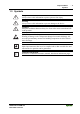
Important Notes Symbols • 9 1.3 Symbols Danger Always observe this information to protect persons from injury. Warning Always observe this information to prevent damage to the device. Attention Marginal conditions that must always be observed to ensure smooth and efficient operation. ESD (Electrostatic Discharge) Warning of damage to the components through electrostatic discharge. Observe the precautionary measure for handling components at risk of electrostatic discharge.
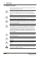
• Important Notes Safety Information 1.4 Safety Information When connecting the device to your installation and during operation, the following safety notes must be observed: Danger The WAGO-I/O-SYSTEM 750 and its components are an open system. It must only be assembled in housings, cabinets or in electrical operation rooms. Access is only permitted via a key or tool to authorized qualified personnel.
Important Notes Font Conventions • 11 Warning For components with ETHERNET/RJ-45 connectors: Only for use in LAN, not for connection to telecommunication circuits. 1.5 Font Conventions italic Names of paths and files are marked in italic. e.g.: C:\Programs\WAGO-IO-CHECK italic Menu items are marked in bold italic. e.g.: Save \ A backslash between two names characterizes the selection of a menu point from a menu. e.g.: File \ New END Press buttons are marked as bold with small capitals e.g.
• Important Notes Scope 1.7 Scope This manual describes the field bus independent WAGO I/O SYSTEM 750 with the programmable BACnet/IP Controller. Item.-No. Description 750-830 BACnet/IP Controller 1.
System Description Technical Condition of the Devices • 13 2 The WAGO-I/O-SYSTEM 750 2.1 System Description The WAGO-I/O-SYSTEM 750 is a modular, field bus independent I/O system. It is comprised of a field bus coupler/controller (1) and connected field bus modules (2) for any type of signal. Together, these make up the field bus node. The end module (3) completes the node. Fig.
• Technical Data Technical Condition of the Devices 2.2 Technical Data Mechanic Material Polycarbonate, Polyamide 6.
Technical Data Technical Condition of the Devices • 15 Safe electrical isolation Air and creepage distance acc. to IEC 60664-1 Degree of pollution acc. To IEC 61131-2 2 Degree of protection Degree of protection IP 20 Electromagnetic compatibility Immunity to interference for industrial areas acc. to EN 61000-6-2 (2001) Test specification Test values Strength class Evaluation criteria EN 61000-4-2 ESD 4 kV/8 kV (contact/air) 2/3 B EN 61000-4-3 electromagnetic fields 10 V/m 80 MHz ...
• Technical Data Technical Condition of the Devices Mechanical strength acc. to IEC 61131-2 Test specification Frequency range Limit value IEC 60068-2-6 vibration 5 Hz ≤ f < 9 Hz 1.75 mm amplitude (permanent) 3.5 mm amplitude (short term) 9 Hz ≤ f < 150 Hz 0.5 g (permanent) 1 g (short term) Note on vibration test: a) Frequency change: max.
Technical Data Technical Condition of the Devices • 17 For Products of the WAGO-I/O-SYSTEM 750 with ship specific approvals supplementary guidelines are valid: Electromagnetic compatibility Immunity to interference acc. to Germanischer Lloyd (2003) Test specification Test values Strength class Evaluation criteria IEC 61000-4-2 ESD 6 kV/8 kV (contact/air) 3/3 B IEC 61000-4-3 electromagnetic fields 10 V/m 80 MHz ...
• Technical Data Technical Condition of the Devices Range of application Required specification emission of interference Required specification immunity to interference Industrial areas EN 61000-6-4 (2001) EN 61000-6-2 (2001) Residential areas EN 61000-6-3 (2001)*) EN 61000-6-1 (2001) *) The system meets the requirements on emission of interference in residential areas with the field bus coupler/controller for: ETHERNET 750-342/-841/-842/-860 LonWorks 750-319/-819 CANopen 750-337/-837 Devic
Technical Data Technical Condition of the Devices • 19 Dimensions 01 02 A A A C C B B A C B D D A C C B D B D D 24V 0V 100 + + - 35 - 12 24 64 65 51 Side view Fig. 2-2: Dimensions Dimensions in mm g01xx05e Note The illustration shows a standard coupler. For detailed dimensions, please refer to the technical data of the respective coupler/controller.
• Manufacturing Number Technical Condition of the Devices 2.3 Manufacturing Number The manufacturing number indicates the delivery status directly after production. This number is part of the lateral marking on the component. In addition, starting from calendar week 43/2000 the manufacturing number is also printed on the cover of the configuration and programming interface of the field bus coupler or controller.
Component Update Technical Condition of the Devices • 21 2.4 Component Update For the case of an Update of one component, the lateral marking on each component contains a prepared matrix. This matrix makes columns available for altogether three updates to the entry of the current update data, like production order number (NO; starting from calendar week 13/2004), update date (DS), software version (SW), hardware version (HW) and the firmware loader version (FWL, if available).
• Mechanical Setup Installation Position 2.6 Mechanical Setup 2.6.1 Installation Position Along with horizontal and vertical installation, all other installation positions are allowed. Attention In the case of vertical assembly, an end stop has to be mounted as an additional safeguard against slipping. WAGO item 249-116 End stop for DIN 35 rail, 6 mm wide WAGO item 249-117 End stop for DIN 35 rail, 10 mm wide 2.6.
Mechanical Setup Assembly onto Carrier Rail 2.6.3 • 23 Assembly onto Carrier Rail 2.6.3.1 Carrier Rail Properties All system components can be snapped directly onto a carrier rail in accordance with the European standard EN 50022 (DIN 35). Warning WAGO Kontakttechnik GmbH & Co. KG supplies standardized carrier rails that are optimal for use with the I/O system. If other carrier rails are used, then a technical inspection and approval of the rail by WAGO Kontakttechnik GmbH & Co. KG should take place.
• Mechanical Setup Spacing 2.6.3.2 WAGO DIN Rail WAGO carrier rails meet the electrical and mechanical requirements. 2.6.4 Item Number Description 210-113 /-112 35 x 7.5; 1 mm; steel yellow chromated; slotted/unslotted 210-114 /-197 35 x 15; 1.5 mm; steel yellow chromated; slotted/unslotted 210-118 35 x 15; 2.3 mm; steel yellow chromated; unslotted 210-198 35 x 15; 2.3 mm; copper; unslotted 210-196 35 x 7.
Mechanical Setup Plugging and Removal of the Components 2.6.5 • 25 Plugging and Removal of the Components Warning Before work is done on the components, the voltage supply must be turned off. In order to safeguard the coupler/controller from jamming, it should be fixed onto the carrier rail with the locking disc To do so, push on the upper groove of the locking disc using a screwdriver.
• 2.6.6 Mechanical Setup Assembly Sequence Assembly Sequence All system components can be snapped directly on a carrier rail in accordance with the European standard EN 50022 (DIN 35). The reliable positioning and connection is made using a tongue and groove system. Due to the automatic locking, the individual components are securely seated on the rail after installing. Starting with the coupler/controller, the bus modules are assembled adjacent to each other according to the project planning.
Mechanical Setup Internal Bus/Data Contacts 2.6.7 • 27 Internal Bus/Data Contacts Communication between the coupler/controller and the bus modules as well as the system supply of the bus modules is carried out via the internal bus. It is comprised of 6 data contacts, which are available as self-cleaning gold spring contacts. Fig.
• 2.6.8 Mechanical Setup Power Contacts Power Contacts Self-cleaning power contacts , are situated on the side of the components which further conduct the supply voltage for the field side. These contacts come as touchproof spring contacts on the right side of the coupler/controller and the bus module. As fitting counterparts the module has male contacts on the left side. Danger The male contacts are sharp-edged. Handle the module carefully to prevent injury.
Mechanical Setup Wire Connection 2.6.9 • 29 Wire Connection All components have CAGE CLAMP® connections. The WAGO CAGE CLAMP® connection is appropriate for solid, stranded and finely stranded conductors. Each clamping unit accommodates one conductor. Fig. 2-9: CAGE CLAMP® Connection g0xxx08x The operating tool is inserted into the opening above the connection. This opens the CAGE CLAMP®. Subsequently the conductor can be inserted into the opening.
• Power Supply Isolation 2.7 Power Supply 2.7.1 Isolation Within the field bus node, there are three electrically isolated potentials. • Operational voltage for the field bus interface. • Electronics of the couplers/controllers and the bus modules (internal bus). • All bus modules have an electrical isolation between the electronics (internal bus, logic) and the field electronics. Some digital and analog input modules have each channel electrically isolated, please see catalog. Fig.
Power Supply System Supply 2.7.2 • 31 System Supply 2.7.2.1 Connection The WAGO-I/O-SYSTEM 750 requires a 24 V direct current system supply (-15 % or +20 %). The power supply is provided via the coupler/controller and, if necessary, in addition via the internal system supply modules (750-613). The voltage supply is reverse voltage protected. Attention The use of an incorrect supply voltage or frequency can cause severe damage to the component. Fig.
• Power Supply System Supply Attention Resetting the system by switching on and off the system supply, must take place simultaneously for all supply modules (coupler/controller and 750-613). 2.7.2.2 Alignment Recommendation A stable network supply cannot be taken for granted always and everywhere. Therefore, regulated power supply units should be used in order to guarantee the quality of the supply voltage.
Power Supply System Supply Example: • 33 A node with a PROFIBUS Coupler 750-333 consists of 20 relay modules (750-517) and 10 digital input modules (750-405). Current consumption: 20* 90 mA = 1800 mA 10* 2 mA = Sum 1820 mA 20 mA The coupler can provide 1650 mA for the bus modules. Consequently, an internal system supply module (750-613), e.g. in the middle of the node, should be added. Recommendation With the WAGO ProServe® Software smartDESIGNER, the assembly of a field bus node can be configured.
• 2.7.3 Power Supply Field Supply Field Supply 2.7.3.1 Connection Sensors and actuators can be directly connected to the relevant channel of the bus module in 1/4 conductor connection technology. The bus module supplies power to the sensors and actuators. The input and output drivers of some bus modules require the field side supply voltage. The coupler/controller provides field side power (DC 24V). In this case it is a passive power supply without protection equipment.
Power Supply Field Supply • 35 Attention Some bus modules have no or very few power contacts (depending on the I/O function). Due to this, the passing through of the relevant potential is disrupted. If a field supply is required for subsequent bus modules, then a power supply module must be used. Note the data sheets of the bus modules. In the case of a node setup with different potentials, e.g. the alteration from DC 24 V to AC 230V, a spacer module should be used.
• Power Supply Field Supply Warning In the case of power supply modules with fuse holders, only fuses with a maximum dissipation of 1.6 W (IEC 127) must be used. For UL approved systems only use UL approved fuses. In order to insert or change a fuse, or to switch off the voltage in succeeding bus modules, the fuse holder may be pulled out. In order to do this, use a screwdriver for example, to reach into one of the slits (one on both sides) and pull out the holder. Fig.
Power Supply Field Supply • 37 Alternatively, fusing can be done externally. The fuse modules of the WAGO series 281 and 282 are suitable for this purpose. Fig. 2-18: Fuse modules for automotive fuses, series 282 pf66800x Abb. 2-19: Fuse modules for automotive fuses, series 2006 p0xxx13x Fig. 2-20: Fuse modules with pivotable fuse carrier, series 281 pe61100x Abb.
• 2.7.4 Power Supply Supplementary Power Supply Regulations Supplementary Power Supply Regulations The WAGO-I/O-SYSTEM 750 can also be used in shipbuilding or offshore and onshore areas of work (e. g. working platforms, loading plants). This is demonstrated by complying with the standards of influential classification companies such as Germanischer Lloyd and Lloyds Register. Filter modules for 24-volt supply are required for the certified operation of the system. Item No.
Power Supply Supply Example 2.7.5 • 39 Supply Example Attention The system supply and the field supply should be separated in order to ensure bus operation in the event of a short-circuit on the actuator side.
• 2.7.6 Power Supply Power Supply Unit Power Supply Unit The WAGO-I/O-SYSTEM 750 requires a 24 V direct current system supply with a maximum deviation of -15 % or +20 %. Recommendation A stable network supply cannot be taken for granted always and everywhere. Therefore, regulated power supply units should be used in order to guarantee the quality of the supply voltage. A buffer (200 µF per 1 A current load) should be provided for brief voltage dips. The I/O system buffers for approx 1 ms.
Grounding Grounding the DIN Rail • 41 2.8 Grounding 2.8.1 Grounding the DIN Rail 2.8.1.1 Framework Assembly When setting up the framework, the carrier rail must be screwed together with the electrically conducting cabinet or housing frame. The framework or the housing must be grounded. The electronic connection is established via the screw. Thus, the carrier rail is grounded.
• 2.8.2 Grounding Grounding Function Grounding Function The grounding function increases the resistance against disturbances from electro-magnetic interferences. Some components in the I/O system have a carrier rail contact that dissipates electro-magnetic disturbances to the carrier rail. Fig. 2-24: Carrier rail contact g0xxx10e Attention Care must be taken to ensure the direct electrical connection between the carrier rail contact and the carrier rail. The carrier rail must be grounded.
Grounding Grounding Protection 2.8.3 • 43 Grounding Protection For the field side, the ground wire is connected to the lowest connection terminals of the power supply module. The ground connection is then connected to the next module via the Power Jumper Contact (PJC). If the bus module has the lower power jumper contact, then the ground wire connection of the field devices can be directly connected to the lower connection terminals of the bus module.
• Shielding (Screening) General 2.9 Shielding (Screening) 2.9.1 General The shielding of the data and signal conductors reduces electromagnetic interferences thereby increasing the signal quality. Measurement errors, data transmission errors and even disturbances caused by overvoltage can be avoided. Attention Constant shielding is absolutely required in order to ensure the technical specifications in terms of the measurement accuracy.
Assembly Guidelines/Standards WAGO Shield (Screen) Connecting System 2.9.4 • 45 WAGO Shield (Screen) Connecting System The WAGO Shield Connecting system includes a shield clamping saddle, a collection of rails and a variety of mounting feet. Together these allow many different possibilities. See catalog W4 volume 3 chapter 10. Fig. 2-26: WAGO Shield (Screen) Connecting System p0xxx08x, p0xxx09x, and p0xxx10x Fig. 2-27: Application of the WAGO Shield (Screen) Connecting System p0xxx11x 2.
• BACnet/IP Controller 750-830 Description 3 Fieldbus Controller 3.1 BACnet/IP Controller 750-830 3.1.1 Description The 750-830 BACnet Controller connects the WAGO-I/O-SYSTEM with the BACnet protocol. The 750-830 Controller complies with the BACnet device profile "BACnet Building Controller" B-BC in accordance with DIN EN ISO 16484-5 and has 3 functions available internally: 1.
BACnet/IP Controller 750-830 Compatibility • 47 An application program can be created using the WAGO-I/O-PRO CAA software, based on IEC 61131-3. The controller provides 512 KB of program memory, 256 KB of data memory and 24 KB of retain memory for this purpose. Start-up and configuration of the BACnet/IP Controller is performed using the Windows-compliant WAGO BACnet Configurator. For communication via BACnet, the BACnet/IP and BACnet/PTP protocols are supported.
• 3.1.3 BACnet/IP Controller 750-830 Hardware Hardware 3.1.3.1 View BACnet/IP fieldbus connection RJ45 LINK ACT BT MS 01 02 power supply status - system - power contacts A C B D 24V 0V data contacts NS 24V 0V I/O USR bus coupler power supply + + 7 50-830 24V _ _ 0V fieldbus connection RS232 power contacts supply power contacts service interface as a configuration and programming interface (flap open) mode switch Fig.
BACnet/IP Controller 750-830 Hardware • 49 3.1.3.2 Power Supply The power supply is derived from modules with CAGE CLAMP® connections. 24 V power supply (see Fig. 3-1) for system power and power to the field side. The integrated power supply provides the required power to the electronics and the bus modules. An electrically isolated power supply is provided to the fieldbus interface.
• BACnet/IP Controller 750-830 Hardware 3.1.3.3 Fieldbus Connection The connection to the fieldbus is made via an RJ45 connector, which is also called a "Western plug." Wiring for the RJ45 socket on the fieldbus controller adheres to 100BaseTX specifications. It is mandatory to use a twisted pair cable of category 5 as a connecting cable. Cable types S-UTP (Screened Unshielded Twisted Pair) and STP (Shielded Twisted Pair) with a maximum segment length of 100 m can be used. Tab.
BACnet/IP Controller 750-830 Hardware • 51 3.1.3.4 Indicators The operational status for the fieldbus controller and the node is indicated by light emitting diodes (LEDs). These are multi-colored (red, green or red-green (=orange)). BACnet/IP ETHERNET LNK ACT BT MS 01 02 A C B D A B 24V 0V NS I/O USR + + Fig. 3-2: Indicators 750-830 g083002x Tab.
• BACnet/IP Controller 750-830 Hardware 3.1.3.5 Configuration Interface and Programming Interface The configuration interface is located behind the cover flap. It is used for communication with WAGO-I/O-CHECK, WAGO-I/O-PRO CAA and for downloading firmware. Configuration and programming interface Fig. 3-3: Configuration Interface g01xx07e The communication cable (750-920) is connected to the four-pole header.
BACnet/IP Controller 750-830 Hardware • 53 3.1.3.6 Mode Selector Switch The mode selector switch is located behind the cover flap. RUN STOP RESET (pushing down) UPDATE FIRMWARE Mode switch Fig. 3-4: Mode Selector Switch g01xx10e The switch is a push button or sliding switch with three positions and a pushbutton function. The sliding switch is designed for a number of operations in compliance with EN61131T2. Tab.
• BACnet/IP Controller 750-830 Hardware Note The position of the mode selector switch is not important when starting or stopping the PFC application from WAGO-I/O-PRO CAA. Attention Remember that if outputs are set when switching the mode selector switch from "RUN" to "STOP" that these will remain set! Software-side switch offs, e.g. by initiators, are ineffective, because the program is no longer processed. Note The user has the opportunity to define the status of the outputs for STOP.
BACnet/IP Controller 750-830 Operating System 3.1.4 • 55 Operating System 3.1.4.1 Boot-up Notice The mode selector switch may not be set at the bottom position during bootup! The controller begins running up after switching on the power supply or after a reset. The PFC program in the flash memory is then transferred to the RAM.
• BACnet/IP Controller 750-830 Operating System Switching on the supply voltage “I/O” LED is blinking orange Is a PLC program in the Flash memory ? No Yes PLC program transfer from the flash memory to RAM Determination of the I/O modules and the configuration Variables are set to 0 or FALSE or to their initial value, flags remain in the same status. Initialization of the system “I/O” LED is blinking red Test o.k.
BACnet/IP Controller 750-830 Process Image 3.1.5 • 57 Process Image Sections 3.1.5 and 3.1.6 provide a glimpse of the internal functioning, data processing and addressing in MODBUS communication. BACnet process data, on the other hand, are not stored in a fixed, internal process image. Using the connected modules, the BACnet/IP controller creates BACnet objects that represent the process data and that are not located in any directly addressable or visible process image. 3.1.5.
• BACnet/IP Controller 750-830 Process Image Note If a node is changed or expanded, this may result in a new process image structure. The process data addresses would then change. In case of an expansion, the process data of all previous modules has to be taken into account. A memory range of 256 words (word 0 ... 255) is initially available in the controller for the process image of the physical input and output data. For the image of the MODBUS/PFC variables, the memory range of words 256 ...
BACnet/IP Controller 750-830 Process Image • 59 3.1.5.2 Example of an Input Process Image The following figure is an example of an input process image. The configuration comprises 16 digital and 8 analog inputs. The input process image thus has a data length of 8 words for the analog modules and 1 word for the digital modules; i.e., 9 words in total.
• BACnet/IP Controller 750-830 Process Image 3.1.5.3 Example of an Output Data Process Image The following example for the output process image comprises 2 digital and 4 analog outputs. It comprises 4 words for the analog outputs and 1 word for the digital outputs, i.e. 5 words in total. In addition, the output data can also be read back with an offset of 200hex (0x0200) added to the MODBUS address.
BACnet/IP Controller 750-830 Process Image • 61 3.1.5.4 MODBUS Process Data For some bus modules and their different versions, the structure of the process data depends on the fieldbus. When applying the MODBUS protocol, the process image has a word structure (with word alignment). The internal mapping method for data greater than one byte conforms to Intel formats. The modules can be mapped directly via addresses with MODBUS.
• 3.1.6 BACnet/IP Controller 750-830 Data Exchange Data Exchange Exchange of process data takes place with BACnet/IP controllers using the BACnet/IP protocol or the MODBUS protocol. The BACnet/IP controller works according to the client server principle. The client requests services from the server. It subscribes, for example, to changes in value or sets limits for alarm/event reports. With its objects, the server maps and executes the service requests of the client.
BACnet/IP Controller 750-830 Data Exchange • 63 3.1.6.1 Memory Areas Programmable Fieldbus Controller memory area for input data word 0 input modules word 255 I/O modules word 256 MODBUS PFC - IN variables word 511 word 512 input modules word 1275 fieldbus master memory area for output data IEC 61131 program CPU word 0 output modules word 255 word 256 MODBUS PFC - OUT variables word 511 word 512 output modules word 1275 Fig.
• BACnet/IP Controller 750-830 Data Exchange In addition, all output data is mirrored in the BACnet/IP controller to a memory area with the address offset 0x0200 and 0x1000. This makes it possible to read back output values by adding 0x0200 and 0x1000 to the MODBUS address. Other memory areas are also provided in the controller, some of which cannot be accessed by the fieldbus side, however.
BACnet/IP Controller 750-830 Data Exchange • 65 3.1.6.2 Addressing Module inputs and outputs in a controller are addressed internally as soon as they are started. The order in which the connected modules are addressed depends on the type of module that is connected (input module, output module). The process image is formed from these addresses. Note This section explains addressing and internal functioning of a controller with connected modules in more detail.
• BACnet/IP Controller 750-830 Data Exchange 3.1.6.2.1 Addressing of Bus Modules Addressing first references complex modules (modules that occupy several bytes) in accordance with their physical order downstream of the fieldbus controller, i.e., they occupy addresses starting from word 0. Following these is the data for the remaining modules, compiled in bytes (modules that occupy less than one byte). In this process, byte by byte is filled with this data in the physical order.
BACnet/IP Controller 750-830 Data Exchange 3.1.6.2.2 • 67 Example of Addressing Two digital input modules (2 DI), two digital output modules (2 DO) and two analog input modules (2 AI) and two analog output modules (2AO) are connected to one controller. The final element is an end module that is not taken into account for addressing. Tab. 3-6: Example of addressing Count Sequence Module Function Data Width Hardware Address 1. 750-467 2 AI / 0-10 Volt 2 x 16 Bit %IW0 and %IW1 2.
• BACnet/IP Controller 750-830 Data Exchange 3.1.6.2.3 Address Ranges Subdivision of the address ranges for word-by-word addressing in accordance with IEC61131-3: Tab. 3-7: Breakdown of address range Word Data 0-255 Physical bus modules 256-511 MODBUS-PFC variables 512-1275 Other physical bus modules Word 0-255: First address range for the input/output data of the bus module: Tab. 3-8: Address range, word 0 - 255 Data Width Address Bit Byte Word DWord 0.0 ... 0 0.8... 0.15 1 0 1.0 ... 1.
BACnet/IP Controller 750-830 Data Exchange • 69 Word 512-1275: Second address range for the input/output data of the bus module: Tab. 3-10: Address range, word 512 - 1275 Data Width Bit Byte Word DWord Address 512.0. 512.7 1024 512.8... 512.15 1025 512 513.0 .. 513.8... ..... 513.7 513.15 1026 1027 ..... 1274.0.. 1274.8.. 1275.0 ... 1274.7 1274.15 1275.7 2548 2549 2550 513 ..... 1274 ..... 637 ..... ..... 12287.0.. 12287.7 24572 ..... 12287 ..... 6144 256 1275.8... 1275.
• BACnet/IP Controller 750-830 Data Exchange 3.1.6.2.4 Absolute Addressing Direct presentation of individual memory cells (absolute addresses) based on IEC 1131-3 is performed using character strings: Tab. 3-13: Absolute addresses Position 1 2 Prefix % I Q M X* B W D Designation Commentary Introduces an absolute address Input Output Flag Single bit Data width 3 Byte (8 bits) Word (16 bits) Double word (32 bits) Address 4 such as word-by-word: %QW27 (28th word), bit-by-bit: %IX1.
BACnet/IP Controller 750-830 Data Exchange • 71 Calculating addresses (as a function of the word address): Bit address: Byte address: Word address .0 to .15 1st byte: 2 x word 2nd byte: 2 x word address + 1 DWord address Word address (even number) / 2 or Word address (uneven number) / 2, rounded 3.1.6.
• BACnet/IP Controller 750-830 Data Exchange MODBUS master 0x0000 0x6000 0x0000 (0x0200) PIO PII 0x00FF 0x6000 (0x7000) 00x0FF 0x62FC (0x02FF) 0x62FC (0x72FC) Outputs Inputs I/O modules PII = Process Input Image PIO = Process Output Image Programmable Fieldbus Controller Fig. 3-9: Data exchange between MODBUS Master and bus modules g015045e Register functions start at address 0x1000.
BACnet/IP Controller 750-830 Data Exchange • 73 3.1.6.4 Data Exchange between PLC Function (CPU) and Bus Modules The PLC function (CPU) of the PFC uses absolute addresses to access the bus module data directly. The PFC uses absolute addresses to reference the input data. The data can then be processed internally in the controller using the IEC 61131-3 program. Flags are stored in a remanent memory area in this process.
• BACnet/IP Controller 750-830 Data Exchange 3.1.6.5.1 Example of MODBUS/TCP Master and PLC Function (CPU) Data access by the MODBUS/TCP master Access to data by the MODBUS Master is always either by word or by bit. Addressing of the first 256 data words by the bus modules begins with wordby-word and bit-by-bit access at 0.
BACnet/IP Controller 750-830 Data Exchange 3.1.6.5.2 • 75 Juxtaposition of MODBUS/TCP and IEC 61131-3 Addresses 3.1.6.5.2.1 Word Access Tab. 3-15: Word access Method FC3 - Read Multiple Register FC4 – Read Holding Register FC16 – Write Multiple Register WAGO-I/O-SYSTEM 750 BACnet/IP Controller MODBUS Addresses decimal hexadecimal 0... 0x0000 – 255 0x00FF 256... 0x0100 – 511 0x01FF 512 ... 0x0200 – 767 0x02FF 768 ... 0x0300 – 1023 0x03FF illegal address 0x0400 – 0x0FFF 4096...
• BACnet/IP Controller 750-830 Data Exchange 3.1.6.5.2.2 Bit Access Tab. 3-16: Bit access Method FC2 - Read Input Discrete FC1 = FC2 + 0x0200 – Read Coils FC15- Force Multiple Coils MODBUS Addresses decimal hexadecimal 0... 0x0000 – 511 0x01FF 512... 0x0200 – 1023 0x03FF Illegal address 0x0400 – 0x0FFF 4096 … 0x1000 – 8191 0x1FFF 8192 ... 0x2000 – 12287 0x2FFF 12288 ... 0x3000 32767 0x7FFF 32768 ... 0x8000 34295 0x85F7 36864 ... 0x9000 38391 0x95F7 0... 0x0000 – 511 0x01FF 512...
BACnet/IP Controller 750-830 Data Exchange 3.1.6.5.2.
• 3.1.7 BACnet/IP Controller 750-830 Fieldbus Node Start-up Fieldbus Node Start-up This chapter provides a step-by-step description of how to start-up a BACnet fieldbus node. The controller must be assigned an IP address before it can communicate properly, which can be done in one of two way: • 3.1.7.1: Startup using WAGO-ETHERNET-Settings Assigning of IP addresses via the serial communication port • 3.1.7.
BACnet/IP Controller 750-830 Fieldbus Node Start-up • 79 After a brief period, the 'I/O' LED lights up green, meaning the fieldbus controller is operational. If an error occurred during start-up, an error code is indicated by a red, flashing 'I/O' LED.
• BACnet/IP Controller 750-830 Fieldbus Node Start-up 3.1.7.1.3 Testing for Proper Functioning of the Fieldbus Node 1. Set up a (non-serial) link between the client PC and the controller to test communication with the controller and correct assignment of the IP address. The client PC must be equipped with a network card for this. 2. Call up the DOS prompt window: Start / Programs / DOS prompt. 3.
BACnet/IP Controller 750-830 Fieldbus Node Start-up • 81 3.1.7.2 Commissioning with the WAGO BootP Server An IP address and other parameters can be assigned to a coupler/controller in a TCP/IP network using the Bootstrap protocol (BootP). Subnet masks and gateways can also be transferred using this protocol. Protocol communication comprises a client request and a server reply. No IP address is available on commissioning of the controller. By default, the BootP protocol is activated in the controller.
• BACnet/IP Controller 750-830 Fieldbus Node Start-up 3.1.7.2.2 Connecting Client PC and Fieldbus Nodes 1. Connect the installed BACnet/IP controller to the client PC either directly, or using a 10BaseT or 100BaseTX cable via a hub. The controller transfer rate depends on the network data transfer rate of your client PC network card. Note If the fieldbus node is connected directly to the client PC, you will require a crossover cable instead of a straight-through cable (1:1). 2.
BACnet/IP Controller 750-830 Fieldbus Node Start-up • 83 4. In the dialog window that then appears, right click on LAN and open the link Properties. 5. Mark the entry Internet protocol TCP/IP Note If any of these entries are missing, install the required TCP/IP components and restart your PC. You must have the Windows NT installation CD, or the installation CD for Windows 2000/XP to install these components. 6. Then click the Properties button.
• BACnet/IP Controller 750-830 Fieldbus Node Start-up Note It is also possible to assign IP addresses under other operating systems (e.g. under Linux) as well as with other BootP servers. Note The IP address is assigned via straight-through cable, switches, hubs, or via direct link using a crossover cable. Addresses cannot be allocated via router. 3.1.7.2.4.1 BootP Table The BootP table is the database for the BootP server. This table is available as a text file (bootptab.
BACnet/IP Controller 750-830 Fieldbus Node Start-up • 85 The examples shown contain the following information: Tab. 3-17: BootP Table Information Information Meaning node1, node2 Any name for a node can be specified here. ht=1 Here the hardware type of the network is specified. For ETHERNET the hardware type is 1. These numbers are explained in RFC1700. ha=0030DE000100 Specify the hardware address (MAC ID) for the BACnet/IP controllers ha=0030DE000200 here (hexadecimal). ip= 10.1.254.100 ip= 10.1.
• BACnet/IP Controller 750-830 Fieldbus Node Start-up Note To address additional fieldbus nodes, enter a similar text line for each node, with your own specific data. 8. In the menu File select the menu item Save to store the changed settings in the "bootptab.txt" file. 9. Close the editor. 3.1.7.2.4.2 BootP Server 1. On your PC, go to Start and select the menu item Programs \ WAGO Software \ WAGO BootP Server. 2. Click on WAGO BootP server to open the dialog window. 3.
BACnet/IP Controller 750-830 Fieldbus Node Start-up 3.1.7.2.5 • 87 Testing the Function of the Fieldbus Node 1. In order to check communication with the controller and for correct IP address assignment, start the DOS prompt via Start / Programs / Command prompt. 2. Type the command ping using the IP address you have assigned, with the following syntax: ping [space] XXXX . XXXX . XXXX . XXXX Fig. 3-2: Example for a fieldbus node function test G083070e 3.
• BACnet/IP Controller 750-830 Fieldbus Node Start-up 3.1.7.2.6 Deactivating the BootP Protocol By default, the BootP protocol is activated in the controller. When the BootP protocol is activated, the controller expects the BootP server to be permanently available. If there is no BootP server available after a PowerOn reset, the network will remain inactive. You must deactivate the BootP protocol and set a fixed IP address. After that, a BootP server is no longer necessary.
BACnet/IP Controller 750-830 Fieldbus Node Start-up Fig. 3-2: HTML pages of the Web-based management system • 89 G083050e Note If these pages are not displayed for local access to the fieldbus nodes, you must define in the Web browser properties that, as an exception, no proxy server is to be used for the node IP address.
• BACnet/IP Controller 750-830 Fieldbus Node Start-up Fig. 3-3: Port configuration G083052e You are shown a list of all the protocols supported by the controller. By default, the BootP protocol is activated in the controller. 5. Click the box behind BootP to remove the check mark. You have now deactivated the protocol. You can also deactivate any other protocols that you no longer need in the same manner, or select desired protocols and activate them explicitly.
BACnet/IP Controller 750-830 Programming the PFC Using WAGO-I/O-PRO CAA 3.1.8 • 91 Programming the PFC Using WAGO-I/O-PRO CAA Using IEC 61131-3 programming, the 750-830 BACnet/IP Controller can also utilize the function of a PLC in addition to the functions of a fieldbus coupler. Creation of an application program in line with IEC 61131-3 is performed using the programming tool WAGO-I/O-PRO CAA.
• BACnet/IP Controller 750-830 Programming the PFC Using WAGO-I/O-PRO CAA To ensure that you can access all bus module data properly in your new project, first compile the bus module configuration based on the existing fieldbus node hardware and map it in the configuration file "EA-config.xml". This file defines whether write access is permitted to the modules from the IEC 611313 program, from the MODBUS/TCP or from BACnet.
BACnet/IP Controller 750-830 Programming the PFC Using WAGO-I/O-PRO CAA • 93 Note The number of modules that send or receive data must correspond to the existing hardware (except for supply modules, copying modules or end modules, for example). The number of input and output bits or bytes of the individually connected bus modules can be found in the corresponding descriptions of the bus modules.
• BACnet/IP Controller 750-830 Programming the PFC Using WAGO-I/O-PRO CAA Fig. 3-5: Write access over module parameters g083023e After completing these settings you can begin with IEC 61131-3 programming. The "EA-config.xml" configuration file is generated as soon as the project has been transferred. Additional Information: For a detailed description of how to use the WAGO-I/O-PRO CAA software and the I/O Configurator, refer to the online help function for WAGO-I/OPRO CAA.
BACnet/IP Controller 750-830 Programming the PFC Using WAGO-I/O-PRO CAA • 95 The file already contains the following syntax: Fig. 3-6: EA-config.xml P012913x The fourth line contains the necessary information for the first bus module. The entry MAP=“PLC“ assigns write access privileges to the IEC 61131-3 program for the first module. If you wish to change the access rights, replace "PL" with "FB3" as the access privileges from BACnet. 5.
• BACnet/IP Controller 750-830 Programming the PFC Using WAGO-I/O-PRO CAA 3.1.8.2 Creating/Exporting the SYM_XML File Note If you are in the simulation mode you cannot perform configuration of symbols or settings for generating the SYM_XML file. The category Symbol configuration is not available for selection in this case. You can make this category visible by selecting Online \ Logoff in the main menu and removing the check mark in front of Simulation.
BACnet/IP Controller 750-830 Programming the PFC Using WAGO-I/O-PRO CAA • 97 3.1.8.3 ETHERNET Libraries for WAGO-I/O-PRO CAA Various libraries are available in WAGO-I/O-PRO CAA for different IEC 61131-3 programming tasks. These contain modules for universal use and can, thereby, facilitate and speed up the creation of your program. Additional Information All libraries are included on the installation CD for the software WAGO-I/O-PRO CAA in the folder directory: CoDeSys V2.3\Targets\WAGO\Libraries\...
• BACnet/IP Controller 750-830 Programming the PFC Using WAGO-I/O-PRO CAA Additional Information For a detailed description of the function blocks and use of the software, refer to the WAGO-I/O-PRO CAA manual at http://www.wago.com under: Documentation ! WAGO-I/O-SYSTEM 759 ! WAGO-I/O-PRO ! 759-333 or the online Help function for WAGO-I/O-PRO CAA.
BACnet/IP Controller 750-830 Programming the PFC Using WAGO-I/O-PRO CAA • 99 3.1.8.4 General Information about IEC Tasks Note Please note the following information when programming your IEC tasks. • IEC tasks must have different priorities, as otherwise an error will occur during translating of the application program. • An ongoing task may be interrupted by tasks with higher priorities.
• BACnet/IP Controller 750-830 Programming the PFC Using WAGO-I/O-PRO CAA 3.1.8.4.1 IEC Task Sequence 1. Determine the system time (tStart). 2. If no full internal bus cycle has run since the last time the outputs were written: ! Wait until the next internal bus cycle is completed. 3. Reading of inputs and reading back of the outputs from the process image. 4. If the application program has been started. ! Execute the program codes for this task. 5. Writing of the outputs to the process image. 6.
BACnet/IP Controller 750-830 Programming the PFC Using WAGO-I/O-PRO CAA • 101 Tab. 3-19: Task priorities Priority Task 0 Internal bus task, fieldbus task (high) 1 Normal task 2 PLC-Comm task 3 (low) Background task Definition: Processes with the highest priority are identified by the lowest numbers. These processes are handled by all other processes. Additional Information For a detailed description of the programming tool WAGO-I/O-PRO CAA refer to the manual WAGO-I/O-PRO CAA at http://www.
• BACnet/IP Controller 750-830 Programming the PFC Using WAGO-I/O-PRO CAA 3.1.8.5 System Events Fig. 3-7: System events p912277d In place of a task, a system event can also call up a project module for processing. The system events to be employed for this depend on the target system. These events consist of the list of supported standard system events for the control system and any other manufacturer-specific events, which may have been added. Possible events, for example: .
BACnet/IP Controller 750-830 Programming the PFC Using WAGO-I/O-PRO CAA • 103 3.1.8.6 Transfer of IEC 61131-3 Program Transfer from the PC to the controller of the program for the created IEC 61131-3 application can be performed two ways: • Direct transfer via serial RS232 port • Transfer by means of TCP/IP via fieldbus Suitable communication drivers are required for transfer; these can be configured using WAGO-I/O-PRO CAA under Online / Communication parameters.
• BACnet/IP Controller 750-830 Programming the PFC Using WAGO-I/O-PRO CAA The following standard entries are shown in the center dialog window: • • • • • Port: COM1 Baud rate: 19200 Parity: Even Stop-bits: 1 Motorola byteorder: No If necessary, change the entries accordingly by clicking on the respective value and editing it. 5. Confirm these settings by clicking OK The RS232 port is now configured for transferring the application.
BACnet/IP Controller 750-830 Programming the PFC Using WAGO-I/O-PRO CAA 3.1.8.6.2 • 105 Transfer via Fieldbus The physical link between the PC and the controller is set up via fieldbus. An appropriate communication driver is required for data transfer. The driver and its parameters must be entered in the WAGO-I/O-PRO CAA in the dialog window "Communication parameters". 1.
• BACnet/IP Controller 750-830 Programming the PFC Using WAGO-I/O-PRO CAA 3.1.8.7 The Web-Based Management System (WBMS) HTML pages containing information and setting options are stored in the controller as referred to as the Web-based management system. Use the menu on the left to navigate through these pages. Information Click the link "Information" to view status information about your controller and network. Fig.
BACnet/IP Controller 750-830 Programming the PFC Using WAGO-I/O-PRO CAA • 107 ETHERNET Over the "Ethernet" link, you will reach a website on which you can configure the bandwidth limit and transmission rate for ETHERNET communication. With the BACnet/IP Controller, you will use Port 1 while setting the transmission rate ("Speed Configuration") (see Tab. 3-20). Tab. 3-20: Set transmission rate ("Speed Configuration“) Parameter Description Enable Port Deactivates the ETHERNET port.
• BACnet/IP Controller 750-830 Programming the PFC Using WAGO-I/O-PRO CAA A set data transfer rate can be defined for the set mode with the option field "Input/Output Limit Rate." For this, port 3 is the internal ETHERNET port linked to the CPU. Bandwidth limiting configured for Port 3 will not have an effect on the data transfer of ETHERNET Port 1!. Fig.
BACnet/IP Controller 750-830 Programming the PFC Using WAGO-I/O-PRO CAA • 109 TCP/IP Click the link "TCP/IP" to go to a Web site where you can specify the settings for the TCP/IP protocol. This protocol forms the basis for network data transfer. Fig.
• BACnet/IP Controller 750-830 Programming the PFC Using WAGO-I/O-PRO CAA Port Click the "Port" link to go to the "Port configuration" page, where you can activate or deactivate the desired protocol. Normally, FTP, HTTP, MODBUS/UDP, MODBUS/TCP, WAGO Services, and CoDeSys are activated. Fig.
BACnet/IP Controller 750-830 Programming the PFC Using WAGO-I/O-PRO CAA • 111 SNMP Click the link "SNMP" to go to a Web site where you can specify the settings for the simple network management protocol. This protocol forms the basis for transfer of control data. Fig.
• BACnet/IP Controller 750-830 Programming the PFC Using WAGO-I/O-PRO CAA Clock Click the link "Clock" to go to a Web site where you can specify the settings for the internal real-time clock. Here, enter the current time and date and also select standard or daylight saving time. Note The internal clock must be (re)set on initial startup, or after 6 days without power. The "I/O" LED for the controller will flash with the error code 1/10 RTC-Powerfail if the clock is not set.
BACnet/IP Controller 750-830 Programming the PFC Using WAGO-I/O-PRO CAA Fig.
• BACnet/IP Controller 750-830 Programming the PFC Using WAGO-I/O-PRO CAA Security Click the "Security" link to go to a Web site at where you can configure read and/or write access privileges for various user groups using passwords to protect the configuration against unauthorized/inadvertent changes. A distinction is drawn between the following user groups: Tab.
BACnet/IP Controller 750-830 Programming the PFC Using WAGO-I/O-PRO CAA • 115 Features Click the link "Features" to go to a Website at which you can activate or deactivate additional functions. The "Autoreset on system error" function enables an automatic software reset to be conducted when a system error occurs. This function can ensure safe, reliable and continuous operation when activated for areas that are difficult to access (e.g. closed rooms, equipment centers on building roofs).
• BACnet/IP Controller 750-830 Programming the PFC Using WAGO-I/O-PRO CAA MODBUS IP Click the link "Modbus IP" to go to a Web site where you can specify the settings for the MODBUS watchdog. Fig.
BACnet/IP Controller 750-830 Programming the PFC Using WAGO-I/O-PRO CAA • 117 MODBUS RTU Click the link "MODBUS RTU" to go to a Web site where you can specify the settings for the MODBUS/RTU protocol. On this page, you set the baud rate of 9600 (standard), 19200 or 57600. With each byte, a parity bit can also be sent. Errors in data transmission are detected with the aid of the parity bit. A differentiation is made between even (even parity), uneven (odd parity) and no parity testing (no parity).
• BACnet/IP Controller 750-830 Programming the PFC Using WAGO-I/O-PRO CAA BACnet You can set the transmission rate of the internal data bus and the UDP port on the "BACnet" page. In the "UDP Port" field, enter the UDP port for BACnet/IP that is to be used. If you place a check mark in the "Non-adaptive internal data bus transmission rate in ms" box (default setting), the transmission rate will be constant and will not be adapted to the node configuration.
BACnet/IP Controller 750-830 Programming the PFC Using WAGO-I/O-PRO CAA • 119 PLC Click the "PLC" link to access a Web site where you can define the PFC functionality settings for your controller. Use the function "Process image - Set outputs to zero if user program is stopped" to define the status of the outputs when your application program quits. If there is a check in the box for this function, all outputs will be set to zero; if there is no check, the outputs will retain their current value.
• BACnet/IP Controller 750-830 Programming the PFC Using WAGO-I/O-PRO CAA Fig.
BACnet/IP Controller 750-830 Programming the PFC Using WAGO-I/O-PRO CAA • 121 I/O config Click the link "I/O config" to view the configuration and/or write access privileges for the outputs of your fieldbus node. The node structure created using the "WAGO-I/O-PRO CAA I/O Configurator" hardware configuration tool is displayed in the window. If no modules are shown in this window, no hardware configuration and, thus, no allocation of write access privileges have been assigned.
• BACnet/IP Controller 750-830 Programming the PFC Using WAGO-I/O-PRO CAA Fig.
BACnet/IP Controller 750-830 Programming the PFC Using WAGO-I/O-PRO CAA • 123 WebVisu Use the link "WebVisu" to open an HTML page displaying the visualization for your programmed application, provided this has been previously created in WAGO-I/O-PRO CAA and saved to the controller. Fig. 3-22: Web-based Management System: WebVisu A visualization editor is integrated into WAGO-I/O-PRO CAA in order to visualize data of the application programmed with WAGO-I/O-PRO CAA.
• 3.1.9 BACnet/IP Controller 750-830 LED Signaling LED Signaling For on-site diagnostics, the controller has several LEDs that indicate operational status for both the controller and the entire node. BACnet/IP ETHERNET LNK ACT BT MS 01 02 A C B D A B 24V 0V NS I/O USR + + Fig. 3-14:Indicators 750-830 g083002x Three different groups of LEDs are differentiated. Fieldbus status (see section 3.1.9.
BACnet/IP Controller 750-830 LED Signaling • 125 3.1.9.1 Fieldbus Status Communication status via ETHERNET is indicated by the upper-LED group (‘LINK/ACT’, 'BT' ‘MS’, 'NS' and ‘I/O’). Tab.
• BACnet/IP Controller 750-830 LED Signaling 3.1.9.2 Node Status – "I/O" LED Blink Code Tab. 3-23: Node status LED Color Meaning I/O Red /green / orange The "I/O" LED indicates the operational status of the node and signals any errors. After applying the supply voltage, the controller boots up. The red ‘I/O‘ LED blinks. After an error-free run-up, the "I/O" LED stays lit as green. In the event of a failure, the ‘I/O’ LED will blink continuously.
BACnet/IP Controller 750-830 LED Signaling • 127 After elimination of the error, the controller must be restarted by means of switching the power off and on again. Tab. 3-24: Signaling of the "I/O" LED I/O Meaning green Data cycle on the internal bus off No data cycle on the internal bus red Controller hardware defect red flashing During run-up: Internal bus initialized During operation: General internal bus error red cyclical flashing Error message for bus module reset and internal error.
• BACnet/IP Controller 750-830 LED Signaling "I/O" LED Error Messages as Blinking Sequences Error messages are indicated by three consecutive blinking sequences. 1 2 3 Initiation of error indication –Pause– Error code –Pause– Error argument Tab. 3-25: Error messages as blinking sequences – Error codes 1 through 11 Error code 1: "Hardware and configuration error" Error Error description argument 1 Overflow of the internal buffer memory for the inline code. Solution 1.
BACnet/IP Controller 750-830 LED Signaling • 129 Error code 1: "Hardware and configuration error" Error Error description argument 7 8 9 10 11 12 13 Solution Invalid hardwarefirmware combination. 1. Switch off power for the node. Timeout during serial EEPROM access. 1. Switch off power for the node. Bus controller initialization error 1. Switch off power for the node. Buffer power failure real-time clock (RTC) 1. Set the clock. Fault during read access to the real-time clock (RTC) 1.
• BACnet/IP Controller 750-830 LED Signaling Error code 3 “Protocol error internal bus” Error Error description argument Solution 2. Are all modules connected correctly or are there any 750-613 bus modules in the node? 3. Switch off the power for the node. 4. Plug the end module in the middle of the node. Turn on the power supply again. 5. LED continues to flash? Switch off the power and plug the end module into the middle of the first half of the node (toward the controller).
BACnet/IP Controller 750-830 LED Signaling • 131 Error code 4 "Physical error, internal bus" Error Error description argument Solution 6. LED continues to flash? Switch off the power and plug the end module into the middle of the first half of the node (toward the controller). LED not flashing? Switch off the power and plug the end module into the middle of the second half of the node (away from controller). 7. Turn on the power supply again. 8.
• BACnet/IP Controller 750-830 LED Signaling Error code 6 " Node configuration error " Error Error description argument Solution 5 Initialization error of an application protocol 1. Restart the fieldbus coupler by turning the power supply off and on again. 6 Maximum process image size exceeded 1. Reduce the number of bus modules 7 IP address of the bus 1.
BACnet/IP Controller 750-830 LED Signaling • 133 Error code 10 "Error during PLC program processing" Error Error description Solution argument 4 Error while initializing 1. Restart the fieldbus coupler by turning the power PFC Web visualization supply off and on again. 2. Should the error persist, perform a reset (origin) in WAGO-I/O-PRO, retranslate the project again and reload it to the controller. 5 Error when synchronizing the PLC configuration with the internal data bus 1.
• BACnet/IP Controller 750-830 LED Signaling 3.1.9.4 Status supply voltage Tab. 3-26: Status supply voltage LED Color Meaning A green Status of power – system B green Status of power – power jumper contacts (position of LED determined by production) The power supply unit of the controller has two green LEDs that indicate the status of the power supply. LED A (left, top) indicates the 24 V supply for the controller.
BACnet/IP Controller 750-830 Fault behavior • 135 3.1.10 Fault behavior 3.1.10.1 Loss of Fieldbus - MODBUS A fieldbus and, hence, a link failure is recognized when the set reaction time for the watchdog expires without initiation by the higher-order control system. This may occur, for example, when the Master is switched off, or when there is a disruption in the bus cable. An error at the Master can also result in a fieldbus failure. No connection via ETHERNET.
• BACnet/IP Controller 750-830 Fault behavior 3.1.10.2 Internal Bus Error An internal bus failure occurs, for example, if a bus module is removed. If the error occurs during operation, the output modules operate as they do during an internal bus stop. The "I/O" LED flashes red. The controller generates an error message (error code and error argument). If the internal bus failure is resolved, the controller starts up after turning the power off and on again as for a normal startup.
BACnet/IP Controller 750-830 Technical Data • 137 3.1.11 Technical Data System data System data ETHERNET Number of controllers Transmission medium max. length of fieldbus segment max. network length Baud rate Fieldbus coupler connection Protocols Serial system data (BACnet PTP)* Baud rate max. length of fieldbus segment Fieldbus coupler connection Programming IEC 61131-3-3 BACnet device profile Limited by ETHERNET specification Twisted Pair S-UTP 100 W CAT 5 100 m acc. to IEEE 802.3 standard acc.
• BACnet/IP Controller 750-830 Technical Data Technical Data Voltage via power jumper contacts Current via power jumper contacts max BACnet implementation acc. to Fieldbus (MODBUS/TCP) Input process image max Output process image max Input variables max Output variables max Operating temperature Wire connection Cross sections Stripped lengths Dimensions (mm) W x H x L Weight Storage temperature Relative humidity (without condensation) DC 24 V (-25 % ...
BACnet/IP Controller 750-830 BACnet Building Controller (B-BC) • 139 3.1.12 BACnet Building Controller (B-BC) The BACnet Standard 135-2004 describes six BACnet device profiles. Any device that implements all the required BACnet capabilities for a particular device type and interoperability area may claim to be a device of that particular device profile. Devices may also provide additional capabilities.
• BACnet/IP Controller 750-830 BACnet Building Controller (B-BC) • • • • Ability to synchronize its internal clock upon request Ability to perform re-initialization upon request Ability to upload its configuration and allow it to be subsequently restored Commands for half routers for establishing and breaking off connections Tab. 3-27: BIBBs of the B-BC shows the minimum requirement for the BIBBs for the B-BC in general as well as additional BIBBs implemented by the WAGO BACnet/IP Controller. Tab.
BACnet/IP Controller 750-830 BACnet Building Controller (B-BC) 3.1.12.1.1.1 • 141 Data Sharing BIBBs These BIBBs prescribe the BACnet capabilities required to interoperably perform the data sharing functions. Data Sharing - ReadProperty-A (DS-RP-A) The A device is a user of data from device B. BACnet Service Requests ReadProperty x Execute Data Sharing-ReadProperty-B (DS-RP-B) The B device is a provider of data to device A.
• BACnet/IP Controller 750-830 BACnet Building Controller (B-BC) Data Sharing-WriteProperty-B (DS-WP-B) The B device allows a value to be changed by device A. BACnet Service Requests WriteProperty Execute x Data Sharing-WritePropertyMultiple-B (DS-WPM-B) The B device allows multiple values to be changed by device A at one time. BACnet Service Requests WritePropertyMultiple Execute x BIBB Data Sharing COV-A (DS-COV-A) Device A is a user of the COV data from device B.
BACnet/IP Controller 750-830 BACnet Building Controller (B-BC) • 143 Data Sharing COVP-A (DS-COVP-A) Device A is a user of the COV data from device B. BACnet Service Requests SubscribeCOVProperty x Execute ConfirmedCOVNotification x UnconfirmedCOVNotification x The support of subscriptions with limited lifetime is necessary; the support of subscriptions with unlimited lifetime is optional.
• BACnet/IP Controller 750-830 BACnet Building Controller (B-BC) 3.1.12.1.1.2 Alarm and Event Management BIBBs These BIBBs prescribe the BACnet capabilities required to interoperably perform the alarm and event management functions. Alarm and Event-Notification Internal-B (AE-N-I-B) Device B generates notifications about alarms and other events.
BACnet/IP Controller 750-830 BACnet Building Controller (B-BC) 3.1.12.1.1.3 • 145 Scheduling BIBBs These BIBBs prescribe the BACnet capabilities required to interoperably perform the scheduling functions. Scheduling A (SCHED-A) Device A processes schedules and the calendar from device B. Device A must support the BIBBs DS-RP-A and DS-WP-A. Scheduling Internal-B (SCHED-I-B) Device B indicates time and data for the scheduling of values of a certain property of certain objects of the device.
• BACnet/IP Controller 750-830 BACnet Building Controller (B-BC) 3.1.12.1.1.4 Trending BIBBs These BIBBs prescribe the BACnet capabilities required to interoperably perform the trend value processing. Trending-Viewing and Modifying Trends Internal-B (T-VMT-I-B) The B device collects the trend log data records in an internal buffer. Each device-claiming conformance to T-VMT-I-B must be able to support at least one Trend Log object.
BACnet/IP Controller 750-830 BACnet Building Controller (B-BC) 3.1.12.1.1.5 • 147 Device and Network Management BIBBs These Device Management BIBBs prescribe the BACnet capabilities required to interoperably perform the device management functions. The network management BIBBs prescribe the BACnet capabilities required to interoperably perform network management functions.
• BACnet/IP Controller 750-830 BACnet Building Controller (B-BC) Device Management-DeviceCommunicationControl-B (DM-DCC-B) The B device responds to communication control exercised by the A device. BACnet Service Requests DeviceCommunicationControl Execute x Support for requests of a limited duration is required, and support for requests of an indefinite duration is optional. Device Management-TimeSynchronization-B (DM-TS-B) The B device interprets time synchronization messages from the A device.
BACnet/IP Controller 750-830 BACnet Building Controller (B-BC) • 149 Device Management-Backup and Restore-B (DM-BR-B) The B device provides its configuration file to the A device and allows the A device to write this file to recover its configuration in the event of a failure. BACnet Service Requests Execute AtomicReadFile x AtomicWriteFile x ReinitializeDevice x DM-BR-B compliant devices must support the features of device B.
• BACnet/IP Controller 750-830 BACnet Building Controller (B-BC) 3.1.12.2 "Native" Operation of the B-BC If the BACnet/IP Controller is switched on, not all objects that are supported by the system are present.
BACnet/IP Controller 750-830 BACnet Building Controller (B-BC) 3.1.12.2.1 • 151 Analog Input Object The Analog Input object defines a standardized object whose properties represent the externally visible characteristics of an analog input. The Analog Input Object and its properties are summarized in Tab. 3-28. The properties are described in section 6. Tab.
• BACnet/IP Controller 750-830 BACnet Building Controller (B-BC) 3.1.12.2.2 Analog Output Object The Analog Output object defines a standardized object whose properties represent the externally visible characteristics of an analog output. The Analog Output Object and its properties are summarized in Tab. 3-29. The properties are described in section 6. Tab.
BACnet/IP Controller 750-830 BACnet Building Controller (B-BC) 3.1.12.2.3 • 153 Binary Input Object The Binary Input object defines a standardized object whose properties represent the externally visible characteristics of a binary input. A "binary input" is a physical device or hardware input that can be in only one of two distinct states. In this description, those states are referred to as ACTIVE and INACTIVE.
• BACnet/IP Controller 750-830 BACnet Building Controller (B-BC) Property Data type: Default Value Writable via BACnet by means of Time_Delay Unsigned 0 WriteProperty Notification_Class Unsigned 0 WriteProperty Alarm_Value BACnetBinaryPV 1 WriteProperty Event_Enable BACnetEventTransitionBits '111' WriteProperty Acked_Transitions BACnetEventTransitionBits '111' - Notify_Type BACnetNotifyType Alarm (0) WriteProperty Event_Time_Stamps BACnetARRAY[3] for BACnetTimeStamp UNSPEC
BACnet/IP Controller 750-830 BACnet Building Controller (B-BC) 3.1.12.2.4 • 155 Binary Output Object The Binary Output object defines a standardized object whose properties represent the externally visible characteristics of a binary output. A "binary output" is a physical device or hardware output that can be in only one of two distinct states. In this description, those states are referred to as ACTIVE and INACTIVE.
• BACnet/IP Controller 750-830 BACnet Building Controller (B-BC) Property Data type: Default Value Writable via BACnet by means of Minimum_On_Time Unsigned32 1 WriteProperty Priority_Array BACnetPriorityArray - - Relinquish_Default BACnetBinaryPV 0 WriteProperty Time_Delay Unsigned 0 WriteProperty Notification_Class Unsigned 0 WriteProperty Feedback_Value BACnetBinaryPV 0 Event_Enable BACnetEventTransitionBits '111' WriteProperty Acked_Transitions BACnetEventTransitionBi
BACnet/IP Controller 750-830 BACnet Building Controller (B-BC) 3.1.12.2.5 • 157 Calendar Object The Calendar object defines a standardized object used to describe a list of calendar dates, which might be thought of as "holidays," "special events," or simply as a list of dates. The Calendar Object and its properties are summarized in Tab. 3-32. The properties are described in section 6. Tab.
• BACnet/IP Controller 750-830 BACnet Building Controller (B-BC) 3.1.12.2.6 Device Object The Device object defines a standardized object whose properties represent the externally visible characteristics of a BACnet Device. There shall be exactly one Device object in each BACnet Device. A Device object is referenced by its Object_Identifier property, which is not only unique to the BACnet Device that maintains this object but is also unique throughout the BACnet internetwork.
BACnet/IP Controller 750-830 BACnet Building Controller (B-BC) • 159 Property Data type: Default Value Writable via BACnet by means of Device_Address_Binding List for BACnetAddressBinding - - Database_Revision Unsigned - - Configuration_Files BACnetARRAY[N] of the BACnetObjectIdentifier - - Last_Restore_Time BACnetTimeStamp UNSPECIFIED - Backup_Failure_Timeout Unsigned16 10 - Active_COV_Subscriptions List for BACnetCOVSubscription - - WAGO-I/O-SYSTEM 750 BACnet/IP Controller
• BACnet/IP Controller 750-830 BACnet Building Controller (B-BC) 3.1.12.2.7 File Object A File Object is created for each BACnet-relevant file in the file system. The File Object is described in the Standard and defines file properties that are accessed by file access services such as the AtomicReadFile Service. The File Object and its properties are summarized in Tab. 3-34. The properties are described in section 6. Tab.
BACnet/IP Controller 750-830 BACnet Building Controller (B-BC) 3.1.12.2.8 • 161 Schedule Object The Schedule object defines a standardized object used to describe a periodic schedule that may recur during a range of dates, with optional exceptions at arbitrary times on arbitrary dates. The Schedule Object also serves as a binding between these scheduled times and the writing of specified "values" to specific properties of specific objects at those times.
• BACnet/IP Controller 750-830 BACnet Building Controller (B-BC) Properties Data type: Based on IEC Data Types Default Value Writable via BACnet by means of Priority_For_Writing Unsigned(1..
Fieldbus Communication ETHERNET • 163 4 Fieldbus Communication 4.1 ETHERNET 4.1.1 General ETHERNET is a technology, which has been proven and established as an effective means of data transmission in the field of information technology and office communication. Within a short time ETHERNET has also made a successful breakthrough in the area of private PC networks throughout the world. This technology was developed in 1972 by Dr. Robert M. Metcalfe, David R. Boggs, Charles Thacker, Butler W.
• Fieldbus Communication ETHERNET The WAGO ETHERNET TCP/IP fieldbus node does not require any additional master components other than a PC with a network card. So, the fieldbus node can be easily connected to local or global networks using the fieldbus connection. Other networking components such as hubs, switches or repeaters can also be used. However, to establish the greatest amount of “determinism” a switch is recommended.
Fieldbus Communication ETHERNET • 165 4.1.2.1 Transmission Media General ETHERNET transmission standards For transmitting data the ETHERNET standard supports numerous technologies with various parameters (e.g., transmission speed, medium, segment length and type of transmission). Tab. 4-1: ETHERNET Transmission Standards 1Base5 Uses a 24 AWG UTP (twisted pair cable) for a 1Mbps baseband signal for distances up to 500 m (250 m per segment) in a physical star topology.
• Fieldbus Communication ETHERNET 10BaseT, 100BaseTX Either the 10BaseT standard or 100BaseTX can be used for the WAGO ETHERNET fieldbus node. The network architecture is very easy and inexpensive to assemble with SUTP cable as transmission medium or with cables of STP type. Both types of cable can be obtained from any computer dealer.
Fieldbus Communication ETHERNET • 167 Attention The cable length between the node and the hub cannot be longer than 100 m (328 ft.) without adding signal conditioning systems (i.e., repeaters). Various possibilities are described in the ETHERNET standard for networks covering larger distances. 4.1.2.2 Network Topologies In the case of 10BaseT, or 100BaseTX several stations (nodes) are connected using a star topology according to the 10BaseT ETHERNET Standard.
• Fieldbus Communication ETHERNET Tree Topology The tree topology combines characteristics of linear bus and star topologies. It consists of groups of star-configured workstations connected to a linear bus backbone cable. Tree topologies allow for the expansion of an existing network, and enables schools, etc. to configure a network to meet their needs. Fig.
Fieldbus Communication ETHERNET • 169 5-4-3 Rule A consideration in setting up a tree topology using ETHERNET protocol is the 5-4-3 rule. One aspect of the ETHERNET protocol requires that a signal sent out on the network cable must reach every part of the network within a specified length of time. Each concentrator or repeater that a signal goes through adds a small amount of time.
• Fieldbus Communication ETHERNET 4.1.2.3 Coupler Modules There are a number of hardware modules that allow for flexible arrangement for setting up an ETHERNET network. They also offer important functions, some of which are very similar. The following table defines and compares these modules and is intended to simplify the correct selection and appropriate application of them.
Fieldbus Communication ETHERNET 4.1.2.4.1 • 171 Static Configuration of the Transmission Mode Using static configuration, both link partners are set to static transmission rate and duplex mode. The following configurations are possible: • 10 Mbit/s, half duplex • 10 Mbit/s, full duplex • 100 Mbit/s, half duplex • 100 Mbit/s, full duplex 4.1.2.4.2 Dynamic Configuration of the Transmission Mode The second configuration option is the autonegotiation mode which is defined in the IEEE 802.3u standard.
• Fieldbus Communication ETHERNET 4.1.2.5 Important Terms Data security If an internal network (Intranet) is to be connected to the public network (e.g., the Internet) then data security is an extremely important aspect. Undesired access can be prevented by a Firewall. Firewalls can be implemented in software or network components. They are interconnected in a similar way to routers as a switching element between Intranets and the public network.
Fieldbus Communication ETHERNET • 173 Deterministic ETHERNET The TCP/IP software or the user program in each subscriber can limit transmittable messages to make it possible to determine real-time requirements. At the same time the maximum medium message rate (datagrams per second), the maximum medium duration of a message, and the minimum time interval between the messages (waiting time of the subscriber) is limited. Therefore, the delay time of a message is predictable.
• 4.1.3 Fieldbus Communication ETHERNET Network Communication Fieldbus communication between master application and (programmable) fieldbus coupler or controller usually takes place using an implemented fieldbus specific application protocol, e. g. MODBUS TCP (UDP), EtherNet/IP, BACnet, KNXNET/IP, PROFINET, Powerlink, SERCOS III or others.
Fieldbus Communication ETHERNET • 175 data and the resultant increase in processing speed. Many programs use both protocols. Important status information is sent via the reliable TCP connection, while the main stream of data is sent via UDP.
• Fieldbus Communication ETHERNET 4.1.3.
Fieldbus Communication ETHERNET 4.1.3.2.1 • 177 ETHERNET ETHERNET address (MAC-ID) Each WAGO ETHERNET (programmable) fieldbus coupler or controller is provided from the factory with a unique and internationally unambiguous physical ETHERNET address, also referred to as MAC-ID (Media Access Control Identity). This can be used by the network operating system for addressing on a hardware level.
• Fieldbus Communication ETHERNET 4.1.3.2.1.1 Channel access method In the ETHERNET Standard, the fieldbus node accesses the bus using CSMA/CD (Carrier Sense Multiple Access/ Collision Detection). Carrier Sense: The transmitter senses the bus. Multiple Access: Several transmitters can access the bus. Collision Detection: A collision is detected. Each station can send a message once it has established that the transmission medium is free.
Fieldbus Communication ETHERNET Class A: (Net-ID: Byte1, Host-ID: Byte2 - Byte4) 101 . 16 . 232 . e.g.: 01100101 0 00010000 Net-ID • 179 22 11101000 00010110 Host-ID The highest bit in Class A networks is always ‘0’. Meaning the highest byte can be in a range of ’0 0000000’ to ‘0 1111111’. Therefore, the address range of a Class A network in the first byte is always between 0 and 127. Class B: (Net-ID: Byte1 - Byte2, Host-ID: Byte3 - Byte4) 181 . 16 . 232 . 22 e.g.
• Fieldbus Communication ETHERNET Attention Never set all bits to equal 0 or 1 in one byte (byte = 0 or 255). These are reserved for special functions and may not be allocated. Therefore, the address 10.0.10.10 may not be used due to the 0 in the second byte. If a network is to be directly connected to the Internet, only registered, internationally unique IP addresses allocated by a central registration service may be used. These are available from InterNIC (International Network Information Center).
Fieldbus Communication ETHERNET • 181 The standard masks depending upon the respective network class are as follows: Class A Subnet mask: 255 .0 .0 .0 .0 .0 .255 .0 Class B Subnet mask: 255 .255 Class C Subnet mask: 255 .255 Depending on the subnet division the subnet masks may, however, contain other values beyond 0 and 255, such as 255.255.255.128 or 255.255.255.248. Your network administrator allocates the subnet mask number to you.
• Fieldbus Communication ETHERNET Gateway The subnets of the Internet are normally connected via gateways. The function of these gateways is to forward packets to other networks or subnets. This means that in addition to the IP address and network mask for each network card, it is necessary to specify the correct IP address of the standard gateway for a PC or fieldbus node connected to the Internet. You should also be able to obtain this IP address from your network administrator.
Fieldbus Communication ETHERNET 4.1.3.2.2.1 • 183 RAW IP Raw IP manages without protocols such as PPP (point-to-point protocol). With RAW IP, the TCP/IP packets are directly exchanged without handshaking, thus enabling the connection to be established more quickly. However, the connection must beforehand have been configured with a fixed IP address. The advantages of RAW IP are high data transfer rate and good stability. 4.1.3.2.2.
• Fieldbus Communication ETHERNET TCP port numbers TCP can, in addition to the IP address (network and subscriber address), respond to a specific application (service) on the addressed subscriber. For this the applications located on a subscriber, such as a web server, FTP server and others are addressed via different port numbers. Well-known applications are assigned fixed ports to which each application can refer when a connection is built up.
Fieldbus Communication ETHERNET • 185 4.1.3.3 Administration and Diagnosis Protocols In addition to the communication protocols described above, various fieldbus specific application protocols and a view protocols for system administration and diagnosis can be implemented. • • • • • • • BootP HTTP DHCP DNS SNTP FTP SMTP Additional Information You can find a list of the exact available implemented protocols in the chapter "Technical Data" to the fieldbus coupler and/or controller. 4.1.3.3.
• Fieldbus Communication ETHERNET The BOOTP Client allows for dynamic configuring of the network parameters: Parameter Meaning IP address of the client Network address of the (programmable) fieldbus coupler or controller IP address of the router If communication is to take place outside of the local network, the IP address of the routers (gateway) is indicated in this parameter.
Fieldbus Communication ETHERNET 4.1.3.3.2 • 187 HTTP (Hyper Text Transfer Protocol) HTTP is a protocol used by WWW (World Wide Web) servers for the forwarding of hypermedia, texts, images, audio data, etc.Today, HTTP forms the basis of the Internet and is also based on requests and responses in the same way as the BootP protocol. The HTTP server implemented in the (programmable) fieldbus coupler or controller is used for viewing the HTML pages saved in the coupler/controller.
• Fieldbus Communication ETHERNET In the case of configuration of network parameters via the DHCP protocol, the coupler/controller automatically sends a request to a DHCP server after initialization. If there is no response, the request is sent again after 4 seconds, a further one after 8 seconds and again after 16 seconds. If all requests remain unanswered, a blink code is output via the “IO” LED. Transfer of the parameters from the EEPROM is not possible.
Fieldbus Communication ETHERNET 4.1.3.3.6 • 189 FTP-Server (File Transfer Protocol) The file transfer protocol (FTP) enables files to be exchanged between different network stations regardless of operating system. In the case of the ETHERNET coupler/controller, FTP is used to store and read the HTML pages created by the user, the IEC61131 program and the IEC61131 source code in the (programmable) fieldbus coupler or controller. A total memory of 1.5 MB is available for the file system.
• Fieldbus Communication ETHERNET Command Function NLST Gives the directory list RMD Deletes directory PWD Gives the actually path MKD Puts on a directory The TFTP (Trivial File Transfer Protocol) is not supported by some of the couplers/controllers. Additional Information You can find a list of the exact available implemented protocols in the chapter "Technical Data" to the fieldbus coupler and/or controller. 4.1.3.3.
Fieldbus Communication ETHERNET • 191 4.1.3.4 Application Protocols If fieldbus specific application protocols are implemented, then the appropriate fieldbus specific communication is possible with the respective coupler/controller. Thus the user is able to have a simple access from the respective fieldbus on the fieldbus node.
• Fieldbus Communication BACnet/IP 4.2 BACnet/IP 4.2.1 General The "Building Automation and Control Network", BACnet for short, is a standardized and company-neutral network protocol for building automation, and is originally geared towards the area of heating, ventilation and air conditioning (HVAC).
Fieldbus Communication BACnet/IP 4.2.1.2.1 • 193 Objects BACnet offers a unified structure for different areas in the network. Thus, field devices such as probes, controllers of the automation level or even complex control and operating stations of the management level are modeled in the object representation. The 25 objects are tailored specifically to the HVAC sector for building automation services. They contain both physical inputs and outputs and virtual objects. Tab.
• Fieldbus Communication BACnet/IP 4.2.1.2.
Fieldbus Communication BACnet/IP 4.2.1.2.3 • 195 Services BACnet is based on the Client-Server model. The Client makes requests to the Server, which processes the Client's requests and returns a report.
• Fieldbus Communication BACnet/IP • ConfirmedEventNotification Service Informs of an event that has occurred and requests a confirmation • UnconfirmedEventNotification Service Informs of an event that has occurred, but does not request a confirmation (broadcast, multicast) • GetAlarmSummary Service Queries available alarms of a device. The Event_State property of the object cannot be NORMAL in this case. The Notify_Type must be set to ALARM.
Fieldbus Communication BACnet/IP • 197 • WritePropertyMultiple Service Changes the values of several properties of several objects File access (File Access Services) • AtomicReadFile Service Query of a file, which is opened, read and closed again, as a whole or in part. • AtomicWriteFile Service Query of a file, which is opened, written and closed again, as a whole or in part.
• Fieldbus Communication BACnet/IP Virtual terminal services (Virtual Terminal Service) • VT-Open Service Establishes a connection to a network • VT-Close Service Breaks the connection off • VT-Data Service Transmits data between network members 4.2.1.2.3.1 Client-Server Communication In Client-Server communication, Clients and Servers are considered to have different functions. A Clients makes a request as a service user of a Server (service provider).
Fieldbus Communication BACnet/IP • 199 Tab.
• Fieldbus Communication BACnet/IP Caretaker with main switch Property Value Priority Present_Value ON 1 Light switching Property Switch for Value vacacion operation Priority Employee with light switch Property Value Priority Present_Value OFF 7 Present_Value ON 8 _________ _________ Priority array _________ 1 ON _________ 2 _________ 3 _________ 4 _________ 5 _________ 6 _________ 7 OFF _________ 8 ON _________ 9 _________ 10 _________ 11 _________ 12 _________ 13 _________ 14 _________ 15
Fieldbus Communication BACnet/IP _________ _________ Priority Array _________ 1 UP _________ 2 _________ 3 _________ 4 _________ 5 _________ 6 UP _________ 7 DOWN _________ 8 _________ 9 _________ 10 _________ 11 _________ 12 _________ 13 _________ 14 _________ 15 _________ 16 _________ _________ Priority Array _________ 1 NULL _________ 2 _________ 3 _________ 4 _________ 5 _________ 6 NULL _________ 7 DOWN _________ 8 _________ 9 _________ 10 _________ 11 _________ 12 _________ 13 _________ 14 _________ 1
• Fieldbus Communication BACnet/IP 4.2.1.2.4 Interoperability Area (IA) The requirements for the overall operability of the system are divided into 5 areas. These areas establish functions for sub-areas of the requirements and serve as the basis for the evaluation of interoperability. They are called Interoperability Areas (IA). 4.2.1.2.4.1 Data Sharing (DS) For the system-wide, joint processing of data items, e.g. sensor information, target value and parameter changes, facility operation, etc.
Fieldbus Communication BACnet/IP • 203 Example: AE-N-A Alarm and Event-Notification-A The Client (A) processes alarms and notifications. The services ConfirmedEventNotification and UnconfirmedEventNotification are necessary for this. These services enable a report back to the initiator regarding the processability of the event notification. 4.2.1.2.4.3 Scheduling (SCHED) Actions that are to be managed with regard to time can be set through Scheduling. Two basic scheduling processes can be set.
• Fieldbus Communication BACnet/IP 4.2.1.2.4.5 Device Management (DM) Information on state, presence and availability of BACnet devices is exchanged. Communication with certain devices can also be enabled and disabled. Through DM, clock time in the entire system can be synchronized. Software can also be restarted on demand. There are also diverse diagnostic and access possibilities.
Fieldbus Communication BACnet/IP 4.2.1.2.6 • 205 Protocol Implementation Conformance Statement (PICS) The Protocol Implementation Conformance Statement (PICS) describes objects, capabilities and functions that the BACnet device supports. This is a standard document that must be filled in by the manufacturer. When linking different systems, the PICS and the BIBBs and other device features contained therein are compared with one another. 4.2.1.2.
• Fieldbus Communication BACnet/IP Tab.
Fieldbus Communication BACnet/IP 4.2.1.2.8 • 207 BACnet Components in Overview The following illustration explains the connection between the previously named components using the example of a BACnet Building Controller (BBC).
• Fieldbus Communication BACnet/IP 4.2.1.3 Scope of Use in Building Automation The use of BACnet devices has the advantage that many different devices and networks can be simply connected with each other and administrated. In doing so, the BACnet Protocol covers communication on the automation and management levels.
Fieldbus Communication BACnet/IP 4.2.1.4.1 • 209 Automation Level The automation level includes alarm organization and the operation of systems. Areas of use • • • • • 4.2.1.4.2 Monitoring Optimizing Control Regulating Reporting Field Level On this level, individual devices and alarm notifications, e.g. the recording of states and measured values, are controlled. Application notes • Trade shows • Switching • Setting 4.2.1.
• Fieldbus Communication BACnet/IP BACnet Application Layer This layer represents the application layer and interface with the outside. Here, communication takes place via BACnet. BACnet Network Layer On this relay level, data transport via BACnet, PROFIBUS FMS, World-FIP and/or EIBnet takes place. BACnet Virtual Link Layer (BVLL) This layer includes the backup and bit transmission of data. The data can be transmitted using protocols and connection possibilities that are established in the Standard.
Fieldbus Communication BACnet/IP • 211 4.2.1.6 BACnet in the Network There are 2 possibilities for sending reports over networks that are based on the Internet protocol (IP) • IP Message Tunneling • BACnet/IP 4.2.1.6.1 IP Message Tunneling Devices that do not communicate over BACnet/IP or that do not use the interfaces specified by the BACnet Standard for communication need a BACnet Tunneling Router (BTRs).
• Fieldbus Communication BACnet/IP 4.2.1.6.2 BACnet/IP For data transmission via BACnet/IP, each individual BACnet device in a subnet must be IP-capable, i.e. has its own IP address and an IP Protocol Stack. In this way, devices can communicate directly with each other. No tunneling routers are necessary (see Fig. 4-3). BACnet device BACnet device BACnet device IP router Network BACnet device IP router BACnet device BACnet device BACnet device A B Network 1 BACnet device Network 2 Fig.
Fieldbus Communication BACnet/IP 4.2.1.6.2.2 • 213 BACnet/IP in Foreign Networks If a device is connected to one subnet and would like to receive broadcasts from another subnet or send to another subnet, BBMDs are required in both subnets (see Fig. 4-4). For a device to communicate that does not have a BBMD in its own (sub)network and therefore becomes a Foreign Device (FD), the other BACnet/IP (sub)networks must have BBMD/FDs (see Fig. 4-5).
• Fieldbus Communication MODBUS Functions 4.3 MODBUS Functions 4.3.1 General MODBUS is a manufacturer-independent, open fieldbus standard for diverse applications in manufacturing and process automation. The MODBUS protocol is implemented for the transmission of the process image, the fieldbus variables, different settings and information on the controller according to the current Internet Draft of the IETF (Internet Engineering Task Force).
Fieldbus Communication MODBUS Functions • 215 Therefore the MODBUS protocol based essentially on the following basic data types: Data type Length Description Discrete Inputs Coils Input Register Holding Register 1 Bit 1 Bit 16 Bit 16 Bit Digital Inputs Digital Outputs Analog-Input data Analog-Output data For each basic data type one or more „Function codes“ are defined.
Use of the MODBUS Functions The example below uses a graphical view of a fieldbus node to show which MODBUS functions can be used to access data of the process image. DO AO AO DI DI AI AI DI AI DI AI Ethernet ON LINK TxD/RxD ERROR I/O 750-342 4.3.
Fieldbus Communication MODBUS Functions 4.3.3 • 217 Description of the MODBUS Functions All MODBUS functions are executed as follows: A MODBUS TCP master (e.g., a PC) makes a request to the WAGO fieldbus node using a specific function code based on the desired operation. The WAGO fieldbus node receives the datagram and then responds to the master with the proper data, which is based on the master’s request.
• Fieldbus Communication MODBUS Functions 4.3.3.1 Function Code FC1 (Read Coils) This function reads the status of the input and output bits (coils) in a slave device. Request The request specifies the reference number (starting address) and the bit count to read. Example: Read output bits 0 to 7.
Fieldbus Communication MODBUS Functions • 219 4.3.3.2 Function Code FC2 (Read Input Discretes) This function reads the input bits from a slave device. Request The request specifies the reference number (starting address) and the bit count to be read.
• Fieldbus Communication MODBUS Functions 4.3.3.3 Function Code FC3 (Read multiple registers) This function reads the contents of holding registers from a slave device in word format. Request The request specifies the reference number (start register) and the word count (register quantity) of the registers to be read. The reference number of the request is zero based, therefore, the first register starts at address 0.
Fieldbus Communication MODBUS Functions • 221 4.3.3.4 Function code FC4 (Read input registers) This function reads contents of input registers from the slave device in word format. Request The request specifies a reference number (start register) and the word count (register quantity) of the registers to be read. The reference number of the request is zero based, therefore, the first register starts at address 0.
• Fieldbus Communication MODBUS Functions 4.3.3.5 Function Code FC5 (Write Coil) This function writes a single output bit to the slave device. Request The request specifies the reference number (output address) of output bit to be written. The reference number of the request is zero based; therefore, the first coil starts at address 0.
Fieldbus Communication MODBUS Functions • 223 4.3.3.6 Function Code FC6 (Write single register) This function writes the value of one single output register to a slave device in word format. Request The request specifies the reference number (register address) of the first output word to be written. The value to be written is specified in the “Register Value” field. The reference number of the request is zero based; therefore, the first register starts at address 0.
• Fieldbus Communication MODBUS Functions 4.3.3.7 Function Code FC11 (Get comm event counter) This function returns a status word and an event counter from the slave device’s communication event counter. By reading the current count before and after a series of messages, a master can determine whether the messages were handled normally by the slave. Following each successful new processing, the counter counts up.
Fieldbus Communication MODBUS Functions • 225 4.3.3.8 Function Code FC15 (Force Multiple Coils) This function sets a sequence of output bits to 1 or 0 in a slave device. The maximum number is 256 bits. Request The request message specifies the reference number (first coil in the sequence), the bit count (number of bits to be written), and the output data. The output coils are zero-based; therefore, the first output point is 0. In this example 16 bits are set, starting with the address 0.
• Fieldbus Communication MODBUS Functions 4.3.3.9 Function Code FC16 (Write multiple registers) This function writes a sequence of registers in a slave device in word format. Request The Request specifies the reference number (starting register), the word count (number of registers to write), and the register data . The data is sent as 2 bytes per register. The registers are zero-based; therefore, the first output is at address 0.
Fieldbus Communication MODBUS Functions 4.3.3.10 • 227 Function Code FC22 (Mask Write Register) This function manipulates individual bits within a register using a combination of an AND mask, an OR mask, and the register’s current content.
• Fieldbus Communication MODBUS Functions 4.3.3.11 Function Code FC23 (Read/Write multiple registers) This function performs a combination of a read and write operation in a single request. The function can write the new data to a group registers, and then return the data of a different group. Request The reference numbers (addresses) are zero-based in the request message; therefore, the first register is at address 0. The request message specifies the registers to read and write.
Fieldbus Communication MODBUS Functions 4.3.4 • 229 MODBUS Register Mapping The following tables display the MODBUS addressing and the corresponding IEC61131 addressing for the process image, the PFC variables, the NOVRAM data, and the internal variables is represented. Via the register services the states of the complex and digital I/O modules can be determined or changed. Register (Word) Access Reading (with FC3, FC4 and FC23): MODBUS-Address [dec] [hex] 0 0x0000 ... 255 ... 0x00FF 256 0x0100 ... 511 .
• Fieldbus Communication MODBUS Functions MODBUS-Address [dec] [hex] 12288 0x3000 ... 24575 ... 0x5FFF 24576 0x6000 ... 25340 ... 0x62FC 25341 0x62FD ... 28671 ... 0x6FFF 28672 0x7000 ... 29436 ... 0x72FC 29437 0x72FD ... 65535 ... 0xFFFF IEC61131 Address %MW0 ... %MW12287 %QW512 ... %QW1275 %QW512 ... %QW1275 - Memory Range NOVRAM 8kB retain memory (max.
Fieldbus Communication MODBUS Functions • 231 Bit Access Writing (with FC5 and FC15): MODBUS Address [dec] [hex] 0 0x0000 ... 511 ... 0x01FF 512 0x0200 ... 1023 ... 0x03FF 1024 0x0400 ... 4095 ... 0x0FFF 4096 0x1000 ... 8191 ... 0x1FFF 8192 0x2000 ... 12287 ... 0x2FFF 12288 0x3000 ... 32767 ... 0x7FFF 32768 0x8000 ... 34295 ... 0x85F7 34296 0x85F8 ... 36863 ... 0x8FFF 36864 0x9000 ... 38391 ... 0x95F7 38392 0x95F8 ... 65535 ... 0xFFFF 4.3.
• Fieldbus Communication MODBUS Functions Address Access Length (word) Remark 0x1029 0x102A R R 9 1 MODBUS-TCP statistics Number of TCP connections 0x1030 0x1031 R/W W 1 1 Configuration MODBUS/TCP Timeout Read out the MAC-ID of the controller 0x1050 R 3 Diagnosis of the connected I/O Modules 0x2000 0x2001 0x2002 0x2003 0x2004 0x2005 0x2006 0x2007 0x2008 R R R R R R R R R 1 1 1 1 1 1 1 1 1 Constant 0x0000 Constant 0xFFFF Constant 0x1234 Constant 0xAAAA Constant 0x5555 Constant 0x7FFF C
Fieldbus Communication MODBUS Functions • 233 4.3.5.1 Description of the internal variables 4.3.5.1.1 Watchdog (Fieldbus failure) The watchdog monitors the data transfer between the fieldbus master and the controller. Every time the controller receives a specific request (as define in the watchdog setup registers) from the master, the watchdog timer in the controller resets. In the case of fault free communication, the watchdog timer does not reach its end value.
• Fieldbus Communication MODBUS Functions Register address 0x1001 (MODBUS Address 404098) Designation Watchdog function coding mask, function code 1...16, WDFCM_1_161...16 Access read / write Default 0x0000 Description Using this mask, the specific function codes can be configured to reset the watchdog function. The function code can be selected by writing a ‘1’ to the appropriate bit(s) ( 2 (Function code-1) +2 (Function code-1... ). Bit 1001.0 corresponds to function code1, Bit 1001.
Fieldbus Communication MODBUS Functions • 235 Register address 0x1005 (MODBUS Address 404102) Designation Stop Watchdog, WD_AC_STOP_MASK Access read / write Default 0x0000 Description This register is used to stop the watchdog timer by entering a value of 0xAAAA followed by 0x5555. Register address 0x1006 (MODBUS Address 404103) Designation While watchdog is running, WD_RUNNING Access read Default 0x0000 Description Current watchdog status.
• Fieldbus Communication MODBUS Functions Register address 0x100A (MODBUS Address 404107) Designation Alternative watchdog Access read / write Default 0x0000 Description This register provides an alternate way to activate the watchdog timer. Procedure: Write a time value in register 0x1000; then write a 0x0001 into register 0x100A. With the first MODBUS request, the watchdog is started. The watchdog timer is reset with each MODBUS/TCP instruction.
Fieldbus Communication MODBUS Functions • 237 Register address 0x100B Value Save Watchdog Parameter Access write Default 0x0000 Description With writing of '1' in register 0x100B the registers 0x1000, 0x1001, 0x1002 are set on remanent. 4.3.5.2 Diagnostic Functions The following registers can be read to determine errors in the node: Register address 0x1020 (MODBUS Address 404129) Designation LedErrCode Access read Description Declaration of the Error code (see section 3.1.8.
• Fieldbus Communication MODBUS Functions Register address 0x1024 (MODBUS Address 404133) Designation CnfLen.DigitalOut Access read Description Number of digital output bits in the process image Register address 0x1025 (MODBUS Address 404134) Designation CnfLen.
Fieldbus Communication MODBUS Functions • 239 Register address 0x102A (MODBUS Address 404139, with a word count of 1) Designation MODBUS/TCP Connections Access read Description Number of TCP connections Register address 0x1030 (MODBUS Address 404145, with a word count of 1) Designation Configuration MODBUS/TCP Timeout Access read / write Default 0x0000 Description This is the maximum number of milliseconds the fieldbus coupler will allow a MODBUS/TCP connection to stay open without receiving
• Fieldbus Communication MODBUS Functions Examples: 4 Channel Digital Input Module = 0x8401 bit 15 code 1 hex 1 1 1 1 4 3 2 1 10 9 8 7 6 5 4 3 2 1 0 0 0 0 0 1 0 0 0 0 0 0 0 0 1 8 0 4 0 1 2 Channel Digital Output Module = 0x8202 bit 1 1 1 12 11 10 9 5 4 3 code 1 0 0 0 0 hex 2 8 0 1 8 7 6 5 4 3 2 1 0 0 0 0 0 0 0 0 1 0 0 2 Register address 0x2031 (MODBUS Address 408242, with a word count of up to 64) Designation Description of the connected busmodules A
Fieldbus Communication MODBUS Functions • 241 Register address 0x2033 (MODBUS Address 408244, with a word count of up to 63) Designation Description of the connected I/O modules Access Read modules 193 ... 255 Description Length 1-63 words These 63 registers identify the 4th block of I/O modules present (modules 193 to 255). Each module is represented in a word.
• Fieldbus Communication MODBUS Functions 4.3.5.4 Firmware Information The following registers contain information on the firmware of the controller: Register address 0x2010 (MODBUS Address 408209, with a word count of 1) Designation Revision, INFO_REVISION Access Read Description Firmware Index, e. g. 0005 for version 5 Register address 0x2011 (MODBUS Address 408210, with a word count of 1) Value Series code, INFO_SERIES Access Read Description WAGO serial number, e. g.
Fieldbus Communication MODBUS Functions • 243 Register address 0x2021 (MODBUS Address 408226, with a word count of up to 8) Value Description, INFO_DESCRIPTION Access Read Description Time of the firmware version, 8 words Register address 0x2022 (MODBUS Address 408227, with a word count of up to 8) Value Description, INFO_DATE Access Read Description Date of the firmware version, 8 words Register address 0x2023 (MODBUS Address 408228, with a word count of up to 32) Value Description, INFO_LOA
• Fieldbus Communication MODBUS Functions Register address 0x2003 (MODBUS Address 408196) Value Mask 1, GP_AAAA Access Read Description This constant is used to verify that all bits are accessible to the fieldbus master. This will be used together with register 0x2004. Register address 0x2004 (MODBUS Address 408197) Value Mask 1, GP_5555 Access Read Description This constant is used to verify that all bits are accessible to the fieldbus master.
I/O Modules Overview • 245 5 I/O Modules 5.1 Overview All listed bus modules, in the overview below, are available for modular applications with the WAGO-I/O-SYSTEM 750. For detailed information on the I/O modules and the module variations, please refer to the manuals for the I/O modules. You will find these manuals on CD ROM „ELECTRONICC Tools and Docs“ (Item No.: 0888-0412) or at http://www.wago.com under Documentation.
• I/O Modules Overview 750-432, 753-432 4 Channel, DC 24 V, 3.0 ms, 2-conductor connection; high-side switching 750-403, 753-403 4 Channel, DC 24 V, 0.2 ms, 2- to 3-conductor connection; high-side switching 750-433, 753-433 4 Channel, DC 24 V, 0.2 ms, 2-conductor connection; high-side switching 750-422, 753-422 4 Channel, DC 24 V, 2- to 3-conductor connection; high-side switching; 10 ms pulse extension 750-408, 753-408 4 Channel, DC 24 V, 3.
I/O Modules Overview • 247 DI NAMUR 750-435 1 Channel, NAMUR EEx i, proximity switch acc. to DIN EN 50227 750-425, 753-425 2 Channel, NAMUR, proximity switch acc. to DIN EN 50227 750-438 2 Channel, NAMUR EEx i, proximity switch acc. to DIN EN 50227 DI Intruder Detection 750-424, 753-424 5.1.2 2 Channel, DC 24 V, intruder detection Digital Output Modules Tab.
• I/O Modules Overview DO AC/DC 230 V 750-509, 753-509 2 Channel solid state relay, AC/DC 230 V, 300 mA 750-522 2 Channel solid state relay, AC/DC 230 V, 500 mA, 3 A (< 30 s) DO Relay 5.1.3 750-523 1 Channel, AC 230 V, AC 16 A, potential-free, 1 make contact 750-514, 753-514 2 Channel, AC 125 V , AC 0.
I/O Modules Overview AI 0 - 10 V 750-467, 753-467 2 Channel, DC 0 - 10 V, single-ended 750-477, 753-477 2 Channel, AC/DC 0 - 10 V, differential input 750-478, 753-478 2 Channel, DC 0 - 10 V, single-ended 750-459, 753-459 4 Channel, DC 0 - 10 V, single-ended 750-468 4 Channel, DC 0 - 10 V, single-ended AI DC ± 10 V 750-456, 753-456 2 Channel, DC ± 10 V, differential input 750-479, 753-479 2 Channel, DC ± 10 V, differential measurement input 750-476, 753-476 2 Channel, DC ± 10 V, single-ended
• 5.1.4 I/O Modules Overview Analog Output Modules Tab.
I/O Modules Overview 5.1.5 • 251 Special Modules Tab.
• I/O Modules Overview PROFIsafe Modules 750-660/000-001 8FDI 24V DC PROFIsafe; PROFIsafe 8 channel digital input module 750-665/000-001 4FDO 0.5A / 4FDI 24V DC PROFIsafe; PROFIsafe 4 channel digital input and output module 750-666/000-001 1FDO 10A / 2FDO 0.
I/O Modules Overview 5.1.6 System Modules Tab. 5-6: System modules Module Bus Extension 750-627 Module bus extension, end module 750-628 Module bus extension, coupler module DC 24 V Power Supply Modules 750-602 DC 24 V, passive 750-601 DC 24 V, max. 6.3 A, without diagnostics, with fuse-holder 750-610 DC 24 V, max. 6.
• I/O Modules Process Data Architecture for MODBUS/TCP 5.2 Process Data Architecture for MODBUS/TCP With some I/O modules, the structure of the process data is fieldbus specific. In the case of a coupler/controller with MODBUS/TCP, the process image uses a word structure (with word alignment). The internal mapping method for data greater than one byte conforms to the Intel format.
I/O Modules Process Data Architecture for MODBUS/TCP • 255 2 Channel Digital Input Modules 750-400, -401, -405, -406, -410, -411, -412, -427, -438, (and all variations), 753-400, -401, -405, -406, -410, -411, -412, -427 Input Process Image Bit 7 Bit 6 Bit 5 Bit 4 Bit 3 Bit 2 Bit 1 Data bit DI 2 Channel 2 Bit 0 Data bit DI 1 Channel 1 Bit 1 Data bit DI 2 Channel 2 Bit 0 Data bit DI 1 Channel 1 2 Channel Digital Input Modules with Diagnostics 750-419, -421, -424, -425, 753-421, -424, -425 Input Pr
• I/O Modules Process Data Architecture for MODBUS/TCP 4 Channel Digital Input Modules 750-402, -403, -408, -409, -414, -415, -422, -423, -428, -432, -433, 753-402, -403, -408, -409, -415, -422, -423, -428, -432, -433, -440 Input Process Image Bit 7 Bit 6 Bit 5 Bit 4 Bit 3 Data bit DI 4 Channel 4 Bit 2 Data bit DI 3 Channel 3 Bit 1 Data bit DI 2 Channel 2 Bit 0 Data bit DI 1 Channel 1 Bit 2 Data bit DI 3 Channel 3 Bit 1 Data bit DI 2 Channel 2 Bit 0 Data bit DI 1 Channel 1 8 Channel Digital
I/O Modules Process Data Architecture for MODBUS/TCP • 257 2 Channel Digital Output Modules 750-501, -502, -509, -512, -513, -514, -517, -535, (and all variations), 753-501, -502, -509, -512, -513, -514, -517 Output Process Image Bit 7 Bit 6 Bit 5 Bit 4 Bit 3 Bit 2 Bit 1 controls DO 2 Channel 2 Bit 0 controls DO 1 Channel 1 2 Channel Digital Input Modules with Diagnostics and Input Process Data 750-507 (-508), -522, 753-507 The 750-507 (-508), -522 and 753-507 digital output modules have a diagnos
• I/O Modules Process Data Architecture for MODBUS/TCP Input Process Image Bit 7 Bit 6 Bit 5 Bit 4 Bit 3 Diagnostic bit S 3 Channel 2 Bit 2 Diagnostic bit S 2 Channel 2 Bit 1 Diagnostic bit S 1 Channel 1 Bit 0 Diagnostic bit S 0 Channel 1 Bit 1 controls DO 2 Channel 2 Bit 0 controls DO 1 Channel 1 Output Process Image Bit 7 Bit 6 Bit 5 Bit 4 Bit 3 Bit 2 not used not used 4 Channel Digital Output Modules 750-504, -516, -519, -531, 753-504, -516, -531, -540 Output Process Image Bit 7 B
I/O Modules Process Data Architecture for MODBUS/TCP • 259 Output Process Image Bit 7 Bit 6 Bit 5 Bit 4 Bit 3 controls DO 4 Channel 4 Bit 2 controls DO 3 Channel 3 Bit 1 controls DO 2 Channel 2 Bit 0 controls DO 1 Channel 1 Bit 2 controls DO 3 Channel 3 Bit 1 controls DO 2 Channel 2 Bit 0 controls DO 1 Channel 1 8 Channel Digital Output Module 750-530, -536, 753-530, -434 Output Process Image Bit 7 controls DO 8 Channel 8 Bit 6 controls DO 7 Channel 7 Bit 5 controls DO 6 Channel 6 Bit 4 cont
• 5.2.3 I/O Modules Process Data Architecture for MODBUS/TCP Analog Input Modules The hardware of an analog input module has 16 bits of measured analog data per channel and 8 bits of control/status. However, the coupler/controller with MODBUS/TCP does not have access to the 8 control/status bits. Therefore, the coupler/controller with MODBUS/TCP can only access the 16 bits of analog data per channel, which are grouped as words and mapped in Intel format in the Input Process Image.
I/O Modules Process Data Architecture for MODBUS/TCP • 261 4 Channel Analog Input Modules 750-453, -455, -457, -459, -460, -468, (and all variations), 753-453, -455, -457, -459 Input Process Image Offset 5.2.
• I/O Modules Process Data Architecture for MODBUS/TCP 4 Channel Analog Output Modules 750-553, -555, -557, -559, 753-553, -555, -557, -559 Output Process Image Offset 5.2.5 Byte Destination Remark High Byte Low Byte 0 D1 D0 Output Value Channel 1 1 D3 D2 Output Value Channel 2 2 D5 D4 Output Value Channel 3 3 D7 D6 Output Value Channel 4 Specialty Modules WAGO has a host of Specialty I/O modules that perform various functions.
I/O Modules Process Data Architecture for MODBUS/TCP • 263 Input Process Image Offset Byte Destination High Byte Low Byte 0 - S 1 D1 D0 2 D3 D2 Remark Status byte Counter Value Output Process Image Offset Byte Destination High Byte Low Byte 0 - C 1 D1 D0 2 D3 D2 Remark Control byte Counter Setting Value 750-404/000-005 The above Counter Modules have a total of 5 bytes of user data in both the Input and Output Process Image (4 bytes of counter data and 1 byte of control/status).
• I/O Modules Process Data Architecture for MODBUS/TCP 750-638, 753-638 The above Counter Modules have a total of 6 bytes of user data in both the Input and Output Process Image (4 bytes of counter data and 2 bytes of control/status). The two counter values are supplied as 16 bits. The following tables illustrate the Input and Output Process Image, which has a total of 4 words mapped into each image. Word alignment is applied.
I/O Modules Process Data Architecture for MODBUS/TCP • 265 Pulse Width Modules 750-511, (and all variations) The above Pulse Width modules have a total of 6 bytes of user data in both the Input and Output Process Image (4 bytes of channel data and 2 bytes of control/status). The two channel values are supplied as 16 bits. Each channel has its own control/status byte. The following table illustrates the Input and Output Process Image, which has a total of 4 words mapped into each image.
• I/O Modules Process Data Architecture for MODBUS/TCP Serial Interface Modules with Standard Data Format 750-650/000-001, -014, -015, -016 750-651/000-001 750-653/000-001, -006 The above Serial Interface Modules with Standard Data Format have a total of 6 bytes of user data in both the Input and Output Process Image (5 bytes of serial data and 1 byte of control/status). The following table illustrates the Input and Output Process Image, which have a total of 3 words mapped into each image.
I/O Modules Process Data Architecture for MODBUS/TCP • 267 SSI Transmitter Interface Modules 750-630, (and all variations) The above SSI Transmitter Interface modules have a total of 4 bytes of user data in the Input Process Image, which has 2 words mapped into the image. Word alignment is applied.
• I/O Modules Process Data Architecture for MODBUS/TCP 750-634 The above Incremental Encoder Interface module has 5 bytes of input data (6 bytes in cycle duration measurement mode) and 3 bytes of output data. The following tables illustrate the Input and Output Process Image, which has 4 words mapped into each image. Word alignment is applied.
I/O Modules Process Data Architecture for MODBUS/TCP • 269 750-635, 753-635 The above Digital Pulse Interface module has a total of 4 bytes of user data in both the Input and Output Process Image (3 bytes of module data and 1 byte of control/status). The following table illustrates the Input and Output Process Image, which have 2 words mapped into each image. Word alignment is applied.
• I/O Modules Process Data Architecture for MODBUS/TCP Input Process Image Offset Byte Destination Remark High Byte Low Byte 0 D0 S DALI Response Status byte 1 D2 D1 Message 3 DALI Address 3 D4 D3 Message 1 Message 2 Output Process Image Offset Byte Destination Remark High Byte Low Byte 0 D0 C DALI command, DSI dimming value Control byte 1 D2 D1 Parameter 2 DALI Address 3 D4 D3 CommandExtension Parameter 1 EnOcean Radio Receiver 750-642 The EnOcean radio receive
I/O Modules Process Data Architecture for MODBUS/TCP • 271 MP Bus Master Module 750-643 The MP Bus Master Module has a total of 8 bytes of user data in both the Input and Output Process Image (6 bytes of module data and 2 bytes of control/status). The following table illustrates the Input and Output Process Image, which have 4 words mapped into each image. Word alignment is applied.
• I/O Modules Process Data Architecture for MODBUS/TCP Vibration Velocity/Bearing Condition Monitoring VIB I/O 750-645 The Vibration Velocity/Bearing Condition Monitoring VIB I/O has a total of 12 bytes of user data in both the Input and Output Process Image (8 bytes of module data and 4 bytes of control/status). The following table illustrates the Input and Output Process Image, which have 8 words mapped into each image. Word alignment is applied.
I/O Modules Process Data Architecture for MODBUS/TCP • 273 AS-interface Master Module 750-655 The length of the process image of the AS-interface master module can be set to fixed sizes of 12, 20, 24, 32, 40 or 48 bytes. It consists of a control or status byte, a mailbox with a size of 0, 6, 10, 12 or 18 bytes and the AS-interface process data, which can range from 0 to 32 bytes. The AS-interface master module has a total of 6 to maximally 24 words data in both the Input and Output Process Image.
• 5.2.6 I/O Modules Process Data Architecture for MODBUS/TCP System Modules System Modules with Diagnostics 750-610, -611 The 750-610 and 750-611 Supply Modules provide 2 bits of diagnostics in the Input Process Image for monitoring of the internal power supply.
List of all BACnet Properties in Native Operation • 275 6 List of all BACnet Properties in Native Operation This section contains a list of all properties of BACnet Objects that can be used in native operation.
• List of all BACnet Properties in Native Operation Acked_Transitions The difference between the properties "BACnetARRAY" and "List of" is that the elements of a field can be individually accessed through a field index while this is not possible for the elements of a "List of".
List of all BACnet Properties in Native Operation Active_COV_Subscriptions • 277 6.2 Active_COV_Subscriptions Data Type List of BACnetCOVSubscription Object Device Description The Active_COV_Subscriptions property is a List of BACnetCOVSubscription, each of which consists of a Recipient, a Monitored Property Reference, an Issue Confirmed Notifications flag, a Time Remaining value and an optional COV Increment.
• List of all BACnet Properties in Native Operation Alarm_Value 6.4 Alarm_Value Data Type BACnetBinaryPV Object Binary input Description This property, of the type BACnetBinaryPV, specifies the value that the Present_Value property must have before an event is generated. This property is required if intrinsic reporting is supported by this object.
List of all BACnet Properties in Native Operation APDU_Segment_Timeout • 279 6.5 APDU_Segment_Timeout Data Type Unsigned Objects Device Description The APDU_Segment_Timeout property, of type Unsigned, shall indicate the amount of time in milliseconds between retransmission of an APDU segment. The default value for this property shall be 2000 milliseconds. This value cannot be zero if the device object property called Number_Of_APDU_Retries is not zero.
• List of all BACnet Properties in Native Operation Application_Software_Version 6.7 Application_Software_Version Data Type CharacterString Objects Device Description This property, of type CharacterString, identifies the version of application software installed in the machine. The content of this string is a local matter, but it could be a date-andtime stamp, a programmer's name, a host file version number, etc. 6.
List of all BACnet Properties in Native Operation Change_Of_State_Count • 281 6.10 Change_Of_State_Count Data Type Unsigned Objects Binary input, Binary output Description This property, of the type Unsigned, represents the number of times that the Present_Value property has changed state since the Change_Of_State_Count property was most recently set to a zero value. The Change_Of_State_Count property has a range of from 0 to 65535 or greater.
• List of all BACnet Properties in Native Operation Configuration_Files Change_Of_State_Count, or Time_Of_State_Count_Reset is present, then all of these properties must be present. Binary Output: A change in polarity does not lead to a change in state. If one of the optional properties Change_Of_State_Time, Change_Of_State_Count, or Time_Of_State_Count_Reset is present, then all of these properties must be present. 6.
List of all BACnet Properties in Native Operation Data_List • 283 6.15 Data_List Data Type List of BACnetCalendarEntry Objects Calendar Description This property is a List of BACnetCalendarEntry, each of which is either an individual date (Date), range of dates (BACnetDateRange), or month/week-of-month/day-of-week specification (BACnetWeekNDay). If the current date fulfills the criteria of the calendar entry, the current value of the Calendar Object is TRUE.
• List of all BACnet Properties in Native Operation Description • the Present_Value must fall below the High_Limit minus Deadband, and • the Present_Value must exceed the Low_Limit plus the Deadband, and • the Present_Value must remain within this range for a minimum period of time, specified in the Time_Delay property, and • either the HighLimitEnable or LowLimitEnable flag must be set in the Limit_Enable property, and • the TO-NORMAL flag must be enabled in the Event_Enable property.
List of all BACnet Properties in Native Operation Device_Type • 285 may be empty if no device identifier-device address bindings are currently known to the device. 6.20 Device_Type Data Type CharacterString Objects Binary Input, Binary Output, Analog Input, Analog Output Description This property, of type CharacterString, is a text description of the physical device connected to a binary input, binary output, analog input or analog output.
• List of all BACnet Properties in Native Operation Event_Enable 6.23 Event_Enable Data Type BACnetEventTransitionBits Objects Binary Input, Binary Output, Analog Input, Analog Output Description This property, of type BACnetEventTransitionBits, shall convey three flags that separately enable and disable reporting of TO-OFFNORMAL, TO-FAULT, and TO-NORMAL events. In the context of Analog Input objects, transitions to High_Limit and Low_Limit Event_States are considered to be "offnormal" events.
List of all BACnet Properties in Native Operation Exception_Schedule • 287 6.26 Exception_Schedule Data Type BACnetARRAY[N]of BACnetSpecialEvent Objects Scheduler Description This property is a BACnetARRAY of BACnetSpecialEvents. Each BACnetSpecialEvent describes a sequence of schedule actions that takes precedence over the normal day's behavior on a specific day or days.
• List of all BACnet Properties in Native Operation Feedback_Value plies to a given day, the relative priority of the SpecialEvents shall be determined by their EventPriority values. If multiple overlapping SpecialEvents have the same EventPriority value, then the SpecialEvent with the lowest index number in the array shall have higher relative priority. The highest EventPriority is 1 and the lowest is 16. The EventPriority is not related to the Priority_For_Writing property of the Schedule Object.
List of all BACnet Properties in Native Operation File_Size • 289 6.29 File_Size Data Type Unsigned Objects File Description This property, of type Unsigned, indicates the size of the file data in octets. If the size of the file can be changed by writing to the file, and File_Access_Method is STREAM_ACCESS, then this property shall be writable. Writing to the File_Size property with a value less than the current size of the file truncates the file at the specified position.
• List of all BACnet Properties in Native Operation Inactive_Text 6.33 Inactive_Text Data Type CharacterString Objects Binary input, Binary output Description Binary Input: This property, of type CharacterString, characterizes the intended effect of the INACTIVE state of the Present_Value property from the human operator's viewpoint. The content of this string is determined locally, but it is intended to contain a description of the ACTIVE state that can be read by the user.
List of all BACnet Properties in Native Operation Limit_Enable • 291 6.35 Limit_Enable Data Type BACnetLimitEnable Objects Analog input, Analog output Description This property, of type BACnetLimitEnable, shall convey two flags that separately enable and disable reporting of high limit and low limit offnormal events and their return to normal. This property is required if intrinsic reporting is supported by this object. 6.
• List of all BACnet Properties in Native Operation Local_Date 6.37 Local_Date Data Type Date Objects Device Description The Local_Date property, of type Date, shall indicate the date to the best of the device's knowledge. If the BACnet Device does not have any knowledge of time or date, then the Local_Date property shall be omitted. 6.
List of all BACnet Properties in Native Operation Max_APDU_Length_Accepted • 293 6.41 Max_APDU_Length_Accepted Data Type Unsigned Objects Device Description This property, of type Unsigned, is the maximum number of octets that may be contained in a single, indivisible application layer protocol data unit. The value of this property shall be greater than or equal to 50. The value of this property is also subject to the limitations of the data link technology used. 6.
• List of all BACnet Properties in Native Operation Minimum_Off_Time 6.45 Minimum_Off_Time Data Type Unsigned32 Objects Binary output Description This property, of type Unsigned32, represents the minimum number of seconds that the Present_Value shall remain in the INACTIVE state after a write to the Present_Value property causes that property to assume the INACTIVE state. The mechanism used for this is described in the WAGO BACnet/IP Controller 750-830 Manual in the section "Prioritization". 6.
List of all BACnet Properties in Native Operation Modification_Date • 295 6.48 Modification_Date Data Type BACnetDateTime Objects File Description This property, of type BACnetDateTime, indicates the last time this object was modified. A File object shall be considered modified when it is created or written to. 6.
• List of all BACnet Properties in Native Operation Object_Identifier 6.52 Object_Identifier Data Type BACnetObjectIdentifier Objects Calendar, File, Binary input, Binary output, Analog input, Analog output, Device, Scheduler Description This property, of the type BACnetObjectIdentifier, is a numeric code that is used to identify the object. It must be unique within the BACnet Device that maintains it. For the device object, the object identifier must be unique internetwork-wide. 6.
List of all BACnet Properties in Native Operation Object_Type • 297 6.55 Object_Type Data Type BACnetObjectType Objects Device, Calendar, File, Binary input, Binary output, Analog input, Analog output, Scheduler Description This property, of the type BACnetObjectType, indicates membership in a particular object type class. The value of this property for native objects can be DEVICE, CALENDAR, FILE, BINARY_INPUT, BINARY_OUTPUT, ANALOG_INPUT, ANALOG_OUTPUT or SCHEDULE. 6.
• List of all BACnet Properties in Native Operation Polarity Schedule: The Out_Of_Service property, of the type BOOLEAN, indicates whether the internal calculations of the schedule object are used to determine the value of the Present_Value property (TRUE) or not (FALSE). This means that the Present_Value property is decoupled from the internal calculations and will not track changes to other properties when Out_Of_Service is TRUE.
List of all BACnet Properties in Native Operation Present_Value • 299 Tab. 6-7: Interrelationships for the Polarity property Present_Value Polarity Physical state of the input or output Physical state of device INACTIVE NORMAL OFF or INACTIVE not running ACTIVE NORMAL ON or ACTIVE running INACTIVE REVERSE ON or ACTIVE not running ACTIVE REVERSE OFF or INACTIVE running 6.
• List of all BACnet Properties in Native Operation Present_Value Binary Output: For this object, the property of the type BACnetBinaryPV indicates the logical state of the Binary Output. The logical state of the output is either INACTIVE or ACTIVE. The relationship between the Present_Value and the physical state of the output is determined by the Polarity property. Possible states are summarized in Tab. 6-9. Tab.
List of all BACnet Properties in Native Operation Present_Value • 301 The normal calculation of the value of the Present_Value property is illustrated as follows (the actual algorithm used is a local matter but must yield the same results as this one): 1. Determine the Exception_Schedule field element using the highest relative priority (as defined in section 6.26, "Exception_Schedule") that is valid for the current day and whose current value (see method below) is not ZERO.
• List of all BACnet Properties in Native Operation Priority_Array 6.59 Priority_Array Data Type BACnetPriorityArray Objects Binary Output, Analog Output Description This property is a read-only array that contains prioritized values/commands that are in effect for this object. See section 4.2.1.2.3.2 for a description of the prioritization mechanism. 6.60 Priority_For_Writing Data Type Unsigned (1...
List of all BACnet Properties in Native Operation Protocol_Revision • 303 6.62 Protocol_Revision Data Type Unsigned Objects Device Description This property, of the type Unsigned, indicates the minor revision level of the BACnet standard. This value starts at 1 and increases in increments for any substantive change(s) to the BACnet standard that affect device communication or behavior. This value reverts to zero upon each change to the Protocol_Version property.
• List of all BACnet Properties in Native Operation Read_Only 6.65 Read_Only Data Type BOOLEAN Objects File Description This property of the type BOOLEAN indicates whether file data may be changed by a BACnet-AtomicWriteFile service (FALSE) or not (TRUE). 6.66 Record_Count Data Type Unsigned Objects File Description This property, of the type Unsigned, indicates the size of the file data in records. The Record_Count property may be present only if File_Access_Type is RECORD_ACCESS.
List of all BACnet Properties in Native Operation Relinquish_Default • 305 Binary Input: {NO_FAULT_DETECTED, NO_SENSOR, OPEN_LOOP, SHORTED_LOOP, UNRELIABLE_OTHER} Binary Output: {NO_FAULT_DETECTED, NO_OUTPUT, OPEN_LOOP, SHORTED_LOOP, UNRELIABLE_OTHER} Analog Input: {NO_FAULT_DETECTED, NO_SENSOR, OVER_RANGE, UNDER_RANGE, OPEN_LOOP, SHORTED_LOOP, UNRELIABLE_OTHER} Analog Output: {NO_FAULT_DETECTED, OPEN_LOOP, SHORTED_LOOP, NO_OUTPUT, UNRELIABLE_OTHER} Schedule: The property Reliability indicates whether the
• List of all BACnet Properties in Native Operation Resolution 6.69 Resolution Data Type REAL Objects Analog Input, Analog Output Description This property, of the type REAL, indicates the smallest recognizable change in the Present_Value property in engineering units (read-only). 6.70 Schedule_Default Data Type ANY Objects Scheduler Description This property contains a default value for the Present_Value property if no other Schedule Value is valid (see section 6.58, "Present_Value").
List of all BACnet Properties in Native Operation Status_Flags • 307 6.72 Status_Flags Data Type BACnetStatusFlags Objects Binary input, Binary output, Analog input, Analog output, Scheduler Description This property, of type BACnetStatusFlags, represents four Boolean flags that indicate the general "health" of a binary or analog input or output or a scheduler object. Three of the flags (for the schedule object two objects) are associated with the values of other properties of this object.
• List of all BACnet Properties in Native Operation System_Status • Schedule: Logical TRUE (1) if the schedule object has been overridden by some mechanism local to the BACnet Device. In this case, "overridden" is taken to mean that the Present_Value property cannot be changed through BACnet services. Otherwise, the value is logical FALSE (0). OUT_OF_SERVICE has the following meaning: Logical TRUE (1) if the Out_Of_Service property has a value of TRUE, otherwise logical FALSE (0). 6.
List of all BACnet Properties in Native Operation Time_Of_Active_Time_Reset • 309 Analog Input, Analog Output: This property, of the type Unsigned, specifies the minimum period of time in seconds that the Present_Value must remain outside the band defined by the High_Limit and Low_Limit properties before a TO-OFFNORMAL event is generated or within the same band, including the Deadband property, before a TO-NORMAL event is generated. 6.
• List of all BACnet Properties in Native Operation Update_Interval 6.78 Update_Interval Data Type Unsigned Objects Analog Input Description This property, of the type Unsigned, indicates the maximum period of time between updates to the Present_Value in hundredths of a second when the input is not overridden and not out-of-service. 6.
List of all BACnet Properties in Native Operation Vendor_Name • 311 6.81 Vendor_Name Data Type CharacterString Objects Device Description This property, of the type CharacterString, identifies the manufacturer of the BACnet Device. 6.82 Weekly_Schedule Data Type BACnetARRAY[7] for BACnetDailySchedule Objects Scheduler Description This property is a BACnet field with exactly seven elements. Each of the elements 1-7 contains a BACnetDailySchedule.
• Protocol Implementation Conformance Statement (PICS) PICS Content 7 Protocol Implementation Conformance Statement (PICS) All devices conforming to the BACnet protocol shall have a Protocol Implementation Conformance Statement (PICS) that identifies all of the portions of BACnet that are implemented. 7.1 PICS Content A PICS is a written document, created by the manufacturer of a device that identifies the particular options specified by BACnet that are implemented in the device.
Application Examples Test of MODBUS Protocol and Fieldbus Nodes • 313 8 Application Examples 8.1 Test of MODBUS Protocol and Fieldbus Nodes A MODBUS master is required to test for proper functioning of fieldbus nodes. Various PC applications from different manufacturers are offered for this purpose, and you can download some of these from the internet as free demo versions. A program that is very suitable for testing your ETHERNET TCP/IP fieldbus nodes, e.g. ModScan by Win-Tech.
• Application Examples Visualization and Control Using SCADA Software SCADA Systems functions include: visualization and monitoring, data access, trend recording, event and alarm processing, process analysis and specific intervention in a process (control). The WAGO ETHERNET fieldbus nodes provide the requisite process input and output values for this.
Application Examples Visualization and Control Using SCADA Software • 315 Example for MODBUS function codes The MODBUS function codes for National Instruments’ SCADA software “Lookout,” employ 6-bit encoding. For example, with the first bit here representing the function code: Tab.
• Use in Hazardous Environments Foreword 9 Use in Hazardous Environments 9.1 Foreword Today’s development shows that many chemical and petrochemical companies have production plants, production, and process automation machines in operation which use gas-air, vapor-air and dust-air mixtures which can be explosive. For this reason, the electrical components used in such plants and systems must not pose a risk of explosion resulting in injury to persons or damage to property.
Use in Hazardous Environments Classification Meeting CENELEC and IEC • 317 Explosive areas resulting from gases, fumes or mist: • Zone 0 areas are subject to an explosive atmosphere (> 1000 h /year) continuously or for extended periods. • Zone 1 areas can expect the occasional occurrence of an explosive atmosphere (> 10 h ≤ 1000 h /year). • Zone 2 areas can expect the rare or short-term occurrence of an explosive atmosphere (> 0 h ≤ 10 h /year).
• 9.3.2 Use in Hazardous Environments Classification Meeting CENELEC and IEC Device Group In addition, the electrical components for explosive areas are subdivided into two device groups: Device Group I: Device group I includes electrical components for use in below-ground mining operations as well as aboveground systems potentially endangered by mine gas and/or combustible dust. Device Group II: Device Group II includes electrical components for use in all other explosive environments.
Use in Hazardous Environments Classification Meeting CENELEC and IEC 9.3.3 • 319 Unit Categories A further subdivision for device groups is made into categories according to their area of use (zones). Tab.
• 9.3.4 Use in Hazardous Environments Classification Meeting CENELEC and IEC Temperature Classes The maximum surface temperature for electrical components of device group I is 150 °C (danger due to coal dust deposits) or 450 °C (if there is no danger of coal dust deposit). In line with the maximum permissible surface temperature for all ignition protection types, the electrical components are subdivided into temperature classes, as far as electrical components of device group II are concerned.
Use in Hazardous Environments Classification Meeting CENELEC and IEC 9.3.5 • 321 Types of Ignition Protection Ignition protection defines the special measures to be taken for electrical components in order to prevent the ignition of surrounding explosive atmospheres. For this reason a differentiation is made between the following types of ignition protection: Tab.
• Use in Hazardous Environments Classification Meeting CENELEC and IEC • Apparatus with protected contacts "nC" Apparatus with contacts, which close and open a possibly ignitable circuit, in which the contact mechanism is designed so that ignition of a defined potentially explosive atmosphere is prevented. • Energy-limited apparatus "nL" Electrical apparatus, in which circuits and components are designed in accordance with the concept of energy limitation.
Use in Hazardous Environments Classifications Meeting the NEC 500 • 323 9.4 Classifications Meeting the NEC 500 The following classifications as defined in article 500 and 505 of the National Electric Code (NEC) are valid for North America. 9.4.1 Divisions The "Divisions" describe the degree of probability of whatever type of dangerous situation occurring. Here the following assignments apply: Tab. 9-6: Divisions Explosion endangered areas due to combustible gases, fumes, mist and dust: 9.4.
• 9.4.3 Use in Hazardous Environments Classifications Meeting the NEC 500 Temperature Classes Electrical components for explosive areas are differentiated by temperature classes: Tab.
Use in Hazardous Environments Identification • 325 9.5 Identification 9.5.1 For Europe According to CENELEC and IEC Fig. 9.5.1-1: Example for lateral labeling of bus modules (750-400, 2 channel digital input module 24 V DC) p01xx03x Fig. 9.5.1-2: Printing on text detail in accordance with CENELEC and IEC Tab. 9-9: Description of Printing on Printing on Text Description DEMKO 08 ATEX 142851 X IECEx PTB 07.
• 9.5.2 Use in Hazardous Environments Identification For America According to NEC 500 Fig. 9.5.2-3: Example for lateral labeling of bus modules (750-400, 2 channel digital input p01xx03x module 24 V DC) Fig. 9.5.2-4: Printing on text detail in accordance with CENELEC and IEC p01xx05x Tab. 9-10: Description of Printing on Printing on Text Description CL 1 Explosion protection group (condition of use category) DIV 2 Area of application (zone) Grp. ABCD Explosion group (gas group) Op temp.
Use in Hazardous Environments Installation Regulations • 327 9.6 Installation Regulations In the Federal Republic of Germany, various national regulations for the installation in explosive areas must be taken into consideration. The basis for this forms the working reliability regulation, which is the national conversion of the European guideline 99/92/E6. They complemented by the installation regulation EN 60079-14. The following are excerpts from additional VDE regulations: Tab.
• 9.6.1 Use in Hazardous Environments Installation Regulations ANSI/ISA 12.12.01 This equipment is suitable for use in Class I, Division 2, Groups A, B, C, D or non-hazardous locations only. Warning Explosion hazard - substitution of components may impair suitability for Class I, Div. 2. Warning Do not disconnect equipment unless power has been switched off or the area is known to be non-hazardous.
Use in Hazardous Environments Installation Regulations 9.6.2 • 329 TÜV Nord Ex-i applications For operation in zone 2, the WAGO-I/O-System 750-*** must be mounted in an enclosure that fulfills the requirements of the directive 94/9/EG and the relevant standards EN 60079-0 and EN 60079-15. The fulfillment of these requirements must be certified by an appointed office.
• 9.6.3 Use in Hazardous Environments Installation Regulations ATEX and IEC Ex GROUP I, CATEGORY M2 only with a suitable enclosure according to IEC 60079-0 and IEC 60079-1 required by end-user. When used in Category M2 locations, the modules have to be installed in suitable ATEX Category M2 certified enclosures according to EN 60079-0: 2006 and EN 60079-1: 2007. The Fieldbus Independent Modules of the WAGO-I/O-System 750-…/….….
Glossary • 331 Glossary A ASHRAE (American Society of Heating, Refrigerating and AirConditioning Engineers) ASHRAE is an American professional association for HVAC engineering that was founded in 1894. ASHRAE prepares and publishes manuals, magazines, standards and guidelines for the air-conditioning sector. The BACnet protocol has been the standard for ASHRAE since 1995 and was accepted by ANSI in 2004 (ANSI/ASHRAE 135-2004).
• Glossary BACnet Configurator The BACnet Configurator is free software that is used for commissioning and configuration of WAGO BACnet/IP controllers. This includes, among other things, logical structuring of the project and network, addressing of the controller, configuration of the client and the service in every WAGO controller and a value browser (for BACnet object properties).
Glossary • 333 BACstac Function libraries that implement the BACnet protocol and interfaces with well-known high-level languages are known as BACstacs. BACstacs are generally available on the market. BACstacs simplify and accelerate the development of new BACnet devices, as protocol communication at the lowest level is already implemented by BACstac, enabling the developer to build directly upon the application level. Baseband Baseband systems are systems that operate without carrier frequencies, i.e.
• Glossary BIBB (BACnet Interoperability Building Block) A BIBB defines which BACnet features must be implemented in a device for each task. Compared to the BIBBs from different manufacturers, common features represent a basis for interoperability between the devices. BIBBs form the function blocks for the specific interoperability area (IA) and define the functions within this base. A BIBB is formed from the IA in which it is contained, the Service that can be used and the user (client or server).
Glossary • 335 Bridge A bridge runs on Layer 2 of the ISO/OSI model. Although the bridge corresponds to a Switch, it has only one output, however. Bridges separate the network into Segments, allowing the number of nodes to be increased. Corrupt data is filtered out. Telegrams are then sent when the target address is located in the linked Segment. Only the frame of the MAC layer is treated.
• Glossary Coaxial Cable This cable contains one, single conductor and radial shielding for transmitting information. CSMA/CD (Carrier Sense Multiple Access/Collision Detection) Random bus access procedure (Carrier Sense Multiple Access with Collision Detection). When a collision is detected, all subscribers back. After waiting (a random delay time), the subscribers attempt to re-transmit the data.
Glossary • 337 DHCP (Dynamic Host Configuration Protocol) This protocol permits automatic configuration of the network for a computer, and also assigns addresses or sets parameters centrally. The DHCP server uses a fixed IP address pool for automatically assigning random, temporary IP addresses to networked computers (Clients) or couplers/controllers, thus saving considerable configuration work in large networks.
• Glossary E EDE (Electronic Data Exchange) The EDE file serves as a configuration aid for coordinating the functions between devices from different suppliers or commissioning parties. . This file contains the addresses set in the BACnet Configurator and the names of the devices and objects, along with the values for the object properties. Generation of the EDE file for the WAGO BACnet/IP controller can be started directly from the user interface for the BACnet Configurator.
Glossary • 339 F Fieldbus The fieldbus is a dedicated bus for the serial transmission of information. Fieldbus systems connect sensors, actuators and controls from the field level to the management level. Numerous different fieldbus systems have been developed for various purposes. For example, the LON and KNX fieldbus systems are used primarily in building automation, whereas CANbus and Interbus are applied chiefly in the automotive industry.
• Glossary G Gateway Device for connecting two different networks, performs the translation between differing protocols. H Hardware Electronic, electric and mechanical components of a module. Header A portion of the data packet, containing information such as the receiver's address information. Host Originally used to describe a central mainframe computer accessed from other systems. The services provided by the subscriber can be called up by means of local and remote request.
Glossary • 341 Hypertext Document format used by HTTP. Hypertext documents are text files that provide links to other text documents via particular highlighted keywords. I ICMP (Internet Control Message Protocol) ICMP is a protocol for transmission of status information and error messages of the IP, TCP and UDP protocols between IP network nodes. ICMP offers, among other things, the possibility of an echo (ping) request to determine whether a destination is available and is responding.
• Glossary Internet A collection of networks interconnected to each other throughout the world. It is most commonly referred to as the World Wide Web, or simply as the Web. Interoperability Interoperability is the capability of different devices, systems, methods or even organizations to find a common language for mutually achieving a set goal.
Glossary • 343 IP Message Tunneling In addition to BACnet/IP, IP message tunneling is a method for transferring BACnet messages to a network. Communication via IP message tunneling takes place via the BACnet tunneling router (BTR), which is also designated as "Annex H Router" on account of its description in the annex of the BACnet Standard.
• Glossary L LAN (Local Area Network) A LAN is a spatially limited, local network for permanently linking computers over shorter distances. Data transfer can take place via ETHERNET, Token Ring and FDDI, as well as wireless (WLAN). Library Collection of Modules available to the programmer in the WAGO I/O PRO CAA programming tool for creating control programs in accordance with IEC61131-3. LON (Local Operating Network) LON is used as a fieldbus for building automation.
Glossary • 345 N Natives BACnet "Native" BACnet objects are those objects that are recognized by BACnet/IP controllers during run-up, without a configuration being loaded. These objects are created automatically for the plugged binary and analog input and output modules. The configuration for the native objects is loaded from the firmware and an internal database. Besides the BACnet/IP controller, no additional hardware is necessary for integrating BACnet into a network.
• Glossary Operating System An operating system is a software used for managing equipment such as memory and connected devices, and for executing programs. P Parameter Setting Parameterization is defined as the assignment and storage of set-up and configuration data as they are required for the execution of predefined functions. Ping Command When a ping command (ping < IP address) is entered, the ping program ICMP generates echo request packets. It is used to test for node availability.
Glossary • 347 Property Objects are described by specific properties and values. In this manner, object information, such as name, status and behavior of an object can be read. Properties may be editable and readable (R), readable and writable (W) and optionally readable and/or writable (O). Access to object properties is gained using Services. The properties Object_Identifier, Object_Name, Object_Type and Present_Value are common to all Objects.
• Glossary R Repeater Repeaters operate (like hubs, but with only one, instead of several outputs) on Layer 1 of the ISO/OSI model. Repeaters are physical amplifiers without their own processing function. They refresh data without detecting damaged data and forward all signals. Repeaters are used for implementing greater transmission distances, or when the maximum number of nodes of (normally) 64 devices for each twistedpair segment is exceeded.
Glossary • 349 RS232 The RS232 (official designation ANSI/EIA/TIA-232-F-1997) is a serial interface for point-to-point connections. "RS" stands for "Radio Sector", but is frequently translated as "Recommended Standard". Data is transmitted via this interface bit-serial over a data line and received on a different data line. As only one data line is used at a time, the data is transmitted time-delayed consecutively and asynchronously.
• Glossary Service port The service port is located next to the mode switch, behind the cover flap on the controller. This port acts as the configuration and programming interface and is used for communication with WAGO-I/O-CHECK, WAGO-I/O-PRO CAA and for downloading firmware. A special programming cable (750920) is necessary. SMTP (Simple Mail Transfer Protocol) Standard protocol, with which E-mails are sent via Internet.
Glossary • 351 Structured Cabling With structured cabling, maximum permissible cable lengths are defined (EIA/TIA 568, IS 11801) for site, building and floor cabling, with recommendations for topologies also indicated. Subnet A portion of a network that shares the same network address as the other portions. These subnets are distinguished through the subnet mask. Subnet Mask Subnet masks can be used to manipulate the address ranges in the IP address area in reference to the number of subnets and hosts.
• Glossary T TCP (Transport Control Protocol) TCP is a connection-oriented network protocol for the transport layer (Layer 4) of the ISO/OSI model provided with relatively secure transmission mechanisms. TCP/IP Protocol Stack The TCP/IP protocol stack denotes network protocols that enable communication between different networks and topologies. Telnet The Telnet protocol fulfils the function of a virtual terminal.
Glossary • 353 U UDP (Users Datagram Protocol) The user datagram protocol is a communication protocol between two computers and an alternative to TCP (Transmission Control Protocol). As with TCP, UDP communicates via Internet Protocol, although it is somewhat less reliable due to its uncontrolled communication method. URL (Uniform Resource Locator) Address form for Internet files which are mostly applied within the World Wide Web (WWW).
• Glossary W WAGO-I/O-PRO CAA (CoDeSys Automation Alliance) Uniform programming environment, programming tool by WAGO Kontakttechnik GmbH& Co. KG for the generation of a control program as per IEC61131-3 for all programmable fieldbus controllers (PFC). The software enables a program to be created, tested, debugged and started up. The predecessor to the WAGO I/O PRO CAA software is the WAGO I/O PRO 32, Versions 2.1 and 2.2. The new WAGO-I/O-PRO CAA consists of the basic tool "CoDeSys 2.
Literature List • 355 Literature List Switching Technology in the Local Network Mathias Hein Thomson Executive Press ISBN 9781850321668 TCP/IP 2: Running a Successful Network (Data Communications and Networks Series) Kevin Washburn, Jim Evans Addison-Wesley Publishing Company, 1996 ISBN 9780201877113 Local Area Networks - An Introduction to the Technology John E.
• Index Index 1 C 100BaseFX · 164 100BaseT4 · 164 100BaseTX · 46, 50 10BaseT · 46, 165 Cable Category 5 · 165 Crossover · 165 Impedance · 165 Parallel · 165 Carrier rail · 26 Carrier Rail · 23 Client · 334 Client-Server Communication · 197 Coaxial cable · 335 Communication cable · 52 Configuration Functions · 228, 236 Configuration Interface · 52 Constant Registers · 242 Contacts Data · 27 Power · 34 Coupler modules · 169 Crossover cable · 165 CSMA/CD · 177, 335 A Absolute Addressing · 70 Access S
Index F Fault behavior · 134 Field Level · 208 Fieldbus · 337 Connection · 50 Failure · 232 Node · 163 Node start-up · 78 Nodes · 78 Status · 125 Firewall · 171, 337 Firmware Information · 241 Foreign device · 212 Frame · 337 FTP · 47, 62, 338 Function · 338 Function block · 338 Function code · 213, 233, 313, 344 Application example · 314 FC1 · 217 FC11 · 223 FC15 · 224 FC16 · 225 FC2 · 218 FC22 · 226 FC23 · 227 FC3 · 219 FC4 · 220 FC5 · 221 FC6 · 222 G Gateway · 169, 181, 338, 346 H Hardware · 338 Hardw
• Index PFC application · 54 PFC Cycle · 55 Ping command · 345 Port number · 183, 213, 345 Port number 80 · 186 Power contacts · 28, 34 not carried out · 35 Power supply · 49 Power supply unit · 48 Predictable ETHERNET · 172, 345 Prioritization · 197, 345 Priority levels · 198 Process Data · 162 Image · 57, 213 Visualization · 163 Programming interface · 52 Properties · 193, 346 Protocol Implementation Conformance Statement (PICS) · 346 Protocols · 162 BootP · 178 Proxy server · 346 PTP · 209 R Realt
Index WAGO-I/O-SYSTEM 750 BACnet/IP Controller • 359
WAGO Kontakttechnik GmbH & Co. KG Postfach 2880 • D-32385 Minden Hansastraße 27 • D-32423 Minden Phone: 05 71/8 87 – 0 Fax: 05 71/8 87 – 1 69 info@wago.com E-Mail: Web: http://www.wago.