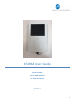
XT4964 User Guide Model: XT4964 FCC ID: GKM-XT4975A IC: 10281A-XT4975A Revision 1 1
Table of Contents Document Change History .......................................................................................... 3 1 Introduction ............................................................................................................ 4 1.1 Feature Matrix ................................................................................................................................................................................. 4 2 Hardware Description ............................
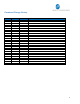
Document Change History Revision Date 1 2 10/24/2019 11/13/2019 Author Changes Johnny Chen Johnny Chen Document Creation based off “XT4975A User Guide v2” Removed Zigbee referenced due to removal of Zigbee HW support 3
1 Introduction The XT4964 is a solar energy harvesting cellular and GPS tracking device supporting long term, remote deployments without the need to replace the rechargeable battery. This user guide describes the physical hardware, associated parts, the different mounting options available, and a quick start-up procedure. 1.
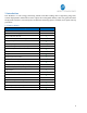
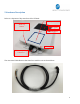
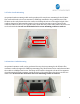
2 Hardware Description Below is a depiction of key interfaces of the XT4964: Device/FCC Label Wake-up Button Solar Panel LED Indicators Gore Vent 8-Pin Bayonet Connector The Associated Cable Harness that interfaces with the unit is shown below: 5
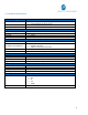
2.1 Hardware Specifications Cellular Technology Options 4G LTE Cat 4 3G UMT/HSDPA/HSUPA 2G GSM/GPRS/EDGE GPS Specification Receiver tracking Sensitivity Accuracy Cold Start Hot Start Power Requirements D.C. Power Current Consumption (4V Supply internal Battery) Max.
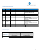
2.2 Cable Harness Description Pin # Wire Color 1 Blue 2 Brown 3 4 Yellow Black 5 Pin Name VBATT GND Functional Description Port Characteristic Ignition Sense Ground 8v to 24v, Internally pulled low 2.4 to 24V, < 0.
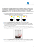
3 Device Mounting Options 3.1 Screw Mounting The XT4964 has two flanges (two holes per) at each end of the housing for screw mounting the device to the mounting surface. 3.
3.3 Trailer Cradle Mounting An optional trailer mounting cradle can be purchased for easy device mounting for the XT4964. The cradle will need to be screw-mounted or VHB Tape mounted to the position desired. The XT4964 can be easily fastened into the cradle via a Phillips head screw. The angled edged of the cradle is designed to withstand the impact of snow scrapers that may come in contact to the cradle if mounted on the top of a typical trailer.
3.5 Device Mounting Guidelines The XT4964 Series devices leverage solar energy to replenish the charge of its battery. Please consider the device mounting guidelines to maximize device solar charging. Also, the XT4964 series uses cellular and GPS technologies whose signal reception quality is depending on mounting location and style. Adhering to these guidelines will optimize the field performance of the XT4964: • If possible, have the solar panel facing directly towards the noon sun.
• • • The XT4964 must be mounted flush to a flat surface. Failing to mount the XT4964 to a flat surface can lead to excessive strain on the top plate which can compromise the device environmental seal and allow ingress of dust and water. When screw mounted, it is recommended that the device is mounted with size #10-24 mechanical bolts and 5.5-6.0 lb.in torque be used. Failure to use the correct bolt size or to apply the correct torque can result in damaging the mounting bracket.
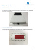
4 Quick Start Guide 4.1 Device Wakeup To start up the device, simply hold the black button located near the circular connector on the side panel of the device for 3 seconds. You should see the blue “C” LED light up and then fade out. The blue LED will blink when the device is successfully connected to the network. Refer to table in section 2.3 for LED behavior. Wake up Button Note: The factory default settings are configured to have the device to sleep within 2 minutes of wake.
4.2 Configuring the Device via SMS 1) 2) 3) 4) 5) 6) 7) 8) Ensure your device is active on your cellular account. Awaken device from sleep XT4964 via the “wake-up” button. If the device needs more power, then supply 12V DC via the red wire of the cable harness. Ensure device cellular LED is blinking based on LED definition in this document.
6) You can now configure the device by sending the XT commands listed in the protocol document of this device. a. Command +XT:1010 configures network settings b. Command +XT:3017 configures the sleep/wake mode for the device. i. The factory defaults for this device is to operate in the sleep timer mode and have a minute of wake time max. You may need to temporarily disable sleep in order to configure the unit uninterrupted by sleep. c.
Regulatory Statements FCC: This equipment with FCC-ID: GKM-XT4964 and IC-ID: 10281A-XT4964, Model: XT4964 is subject to the Federal Communications Commission (FCC) and Industry Canada (IC) rules. NOTICE: Changes or modifications not expressly approved by the party responsible for compliance could void the user's authority to operate the equipment. This device complies with Part 15 of the FCC Rules.
IC: Antenna Statement Under Industry Canada regulations, this radio transmitter may only operate using an antenna of a type and maximum (or lesser) gain approved for the transmitter by Industry Canada. To reduce potential radio interference to other users, the antenna type and its gain should be so chosen that the equivalent isotropically radiated power (e.i.r.p.) is not more than that necessary for successful communication.