
Installation Guide

Veea, Inc. Confidential & Proprietary
3
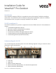
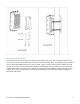
ethernet connection. Use the connectors provided in the installation kit to install the ethernet
connection(s), as needed. Refer to Table 3 for the pinout information and cabling recommendations for
each connection attaching to the lower edge of the VHH10 unit.
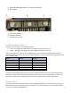
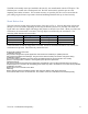
Connector
Pin Diagram
Assignment
AWG
Twisted
Pairs
Power
Pin1, V+, Red
Pin3, V-, Black
Pin4, GND, Green/Yellow
24#
Pin 1&3
Ethernet/PoE
P1, DA+, White/Orange
P2, DA-, Orange
P3, DB+, White/Green
P4, DB-, Green
P5, DD+, White/Brown
P6, DD-, Brown
P7, DC-, White/Blue
P8, DC+, Blue
24#
CAT5e
Pin 1&2
Pin 3&4
Pin 5&6
Pin 7&8
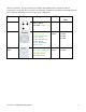
RS232/422/485
Serial
Pin1, RTS, White/Orange
Pin2, CTS, White/Green
Pin3, TXD, Orange
Pin4, RXD, Green
Pin5, GND, Brown
24#
CAT5e
Pin 1&3
Pin 2&4
Table 2