
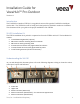
Installation Guide

Veea, Inc. Confidential & Proprietary
2
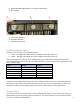
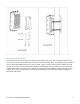
6. RS232/422/485 (M12 female) – for serial IoT connection
7. Reset button
A B C
Figure 2
A. LTE Primary Antenna
B. Bluetooth Antenna
C. LTE Diversity Antenna
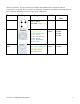
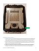
Understanding the Lights
The lights (refer to Figure 1) are named as follows:
1. Lower – This light is the lower of the pair of lights on the side of the unit.
2. Upper – This light is the upper of the pair of lights on the side of the unit.
Each of these lights are either off, on or flashing read, green or blue. The resulting pattern provides
information about the state of the unit. The following table is a partial listing of the status patterns of the
device indicator lights.
State
Lower
Upper
Normal Operation
On Green
On Green
No Power
Off
Off
Bootloader Starting
On Green
Off
Linux Starting
Off
On Green
Reset
Flashing Red
Off
Recovery
Flashing Red
Flashing Red
Table 1
In general, when a light is flashing red, some error condition exists. In that case, the specific pattern on
the indicator lights will tell more details about the specific error. For a complete listing of all the error
conditions and their associated light patterns please refer to the VHH10 User Guide document.
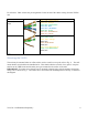
Ethernet Ports
The VHH10 unit has two ethernet ports. The port labeled #4 in Figure 1 above, accepts 802.3bt power
and should be used as the primary gateway connection. The other ethernet port is an optional auxiliary