
Users Manual


LTE Standard Module Series
EC200T Series Mini PCIe Hardware Design
EC200T_Series_Mini_PCIe_Hardware_Design 31 / 54
3.10.1. RI Signal
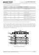
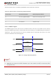
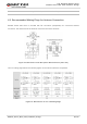
The RI signal can be used to wake up the host. When a URC returns, there will be the following behaviors
on the RI pin after executing AT+QCFG="risignaltype","physical".
Figure 10: RI Behaviors
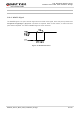
3.10.2. DTR Signal
The DTR signal is used for sleep mode control. It is pulled up by default. When module is in sleep mode,
driving it low can wake up the module. For more details about the preconditions for module to enter sleep
mode, please refer to Chapter 3.4.1.
3.10.3. W_DISABLE# Signal
EC200T Series Mini PCIe provides a W_DISABLE# signal to disable or enable the RF function. The
W_DISABLE# pin is pulled up by default. Its control function for airplane mode is disabled by default, and
AT+QCFG=“airplanecontrol”,1 can be used to enable the function. Driving it low can make the module
enter airplane mode.
The RF function can also be enabled or disabled through AT commands AT+CFUN, and the details are as
follows.
Table 12: Airplane Mode Controlled by Hardware Method
status of the module;
Active low.
WAKE# 1 OC
Wake up the module.
W_DISABLE# RF Function Status Module Operation Mode
High level RF enabled Normal mode
Low level RF disabled Airplane mode