
Users Manual


LTE Standard Module Series
EC200T Series Mini PCIe Hardware Design
EC200T_Series_Mini_PCIe_Hardware_Design 30 / 54
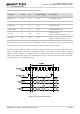
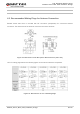
Clock and mode can be configured by AT command, and the default configuration is master mode using
short frame synchronization format with 2048kHz PCM_CLK and 8kHz PCM_SYNC.
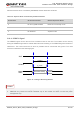
The following figure shows a reference design of PCM interface with an external codec IC.
Figure 9: Reference Circuit of PCM Application with Audio Codec
It is recommended to reserve an RC (R=22Ω, C=22pF) circuit on the PCM signal lines, especially for
PCM_CLK.
3.10. Control and Indication Signals
The following table shows the pin definition of control and indication signals.
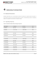
Table 11: Pin Definition of Control and Indication Signals
Pin Name Pin No. I/O Power Domain Description
RI 17 DO 3.3 V Ring indication
DTR 31 DI 3.3 V Data terminal ready
W_DISABLE# 20 DI 3.3 V
Airplane mode control;
Pulled up by default;
Active low.
PERST# 22 DI 3.3 V
Module reset ;
Active low.
LED_WWAN# 42 OC
LED signal for indicating the network
NOTE