
Users Manual


LTE Standard Module Series
EC200T Series Mini PCIe Hardware Design
EC200T_Series_Mini_PCIe_Hardware_Design 28 / 54
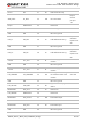
The following table shows the pin definition of the main UART interface.
Table 9: Pin Definition of Main UART Interface
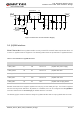
The signal level of main UART interface is 3.3 V. When connecting to the peripheral MCU/RAM,
customers need to pay attention to the signal direction. The reference circuit is as follows:
MCU/ARM
TXD
RXD
UART_RXD
UART_TXD
UART_RTS
UART_CTS
RTS
CTS
GND
Module
GND
Voltage level: 3.3 V
Voltage level: 3.3 V
Figure 7: Reference Circuit of Power Supply
3.9. PCM and I2C Interfaces
EC200T Series Mini PCIe provides one Pulse Code Modulation (PCM) digital interface and one I2C
interface.
The following table shows the pin definition of PCM and I2C interfaces that can be applied in audio codec
design.
Pin Name Pin No. I/O Power Domain Description
UART_RX 11 DI 3.3 V receive
UART_TX 13 DO 3.3 V transmit
UART_CTS 23 DI 3.3 V clear to send
UART_RTS 25 DO 3.3 V request to send