
User's Guide

DTM-02L User’s Guide
Rev.: 1.0
+Update: 23/09/19
Rev. 1.0
Page 4 of 17
This page contains confidential information, which is protected by copyright and is proprietary to DIV
No part of this document may be used, copied, disclosed or conveyed to another party without prior written consent of DIV
Figure
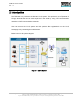
FIGURE 1 LIN-Q SYSTEM .................................................................................................................................. 8
FIGURE 2 DTM-02L TERMINAL ........................................................................................................................ 9
FIGURE 3 DTM-02L TERMINAL ...................................................................................................................... 11
FIGURE 4 I/O CONNECTOR ............................................................................................................................. 12
FIGURE 5 STATUS LED ................................................................................................................................... 14
Table
TABLE 1 DESCRIPTIONS FOR EACH PARTS OF DTM-01 ............................................................................ 11
TABLE 2 PIN DESCRIPTIONS FOR I/O CONNECTOR.................................................................................... 13
TABLE 3 STATUS LED....................................................................................................................................... 14
TABLE 4 DTM-02L SPECIFICATIONS .............................................................................................................. 16