
User's Guide

DTM-02L User’s Guide
Rev.: 1.0
+Update: 23/09/19
Rev. 1.0
Page 13 of 17
This page contains confidential information, which is protected by copyright and is proprietary to DIV
No part of this document may be used, copied, disclosed or conveyed to another party without prior written consent of DIV
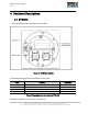
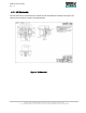
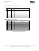
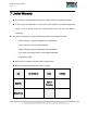
The below table shows the description of the each pin.
CONNECTOR Main (776276-1, Black)
PN
Pin Name
Pin Type
Comments
1
FUEL_ADC
Input
Signal Input Analog (with ADC)
2
CAN Low
Input/Output
CAN Low Signal
3
IGN+
Input
IGN+ Signal Input (Logic)
4
BRK
Input
Brake signal Input (Logic)
5
GND1
Power
Digital Ground
6
SPD
Input
Speed signal Input (Logic)
7
CAN High
Input/Output
CAN High Signal
8
BAT+
Power
Car Battery +
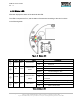
CONNECTOR Sub (776276-2, Natural)
PN
Pin Name
Pin Type
Comments
1
ACC_TXD
Output
RS232C Level TXD Signal (Acc_Sensor)
2
GPI01
Input/Output
Digital Signal Input1/Output1 (Logic)
3
NFC_TXD
Output
RS232C Level TXD Signal (NFC Reader)
4
GPI02
Input/Output
Digital Signal Input2/Output2 (Logic)
5
GND2
Power
Digital Ground
6
ACC_RXD
Input
RS232C Level RXD Signal (Acc_Sensor)
7
GPI03
Input/Output
Digital Signal Input3/Output3 (Logic)
8
NFC_RXD
Input
RS232C Level RXD Signal (NFC Reader)
Table 2 Pin descriptions for I/O connector