
Getting Started Guide


5 | Rev. 0.4
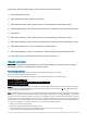
duringcranking and while motor is running. Connect the device’s white/yellow wire here.
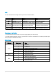
Connector cable color table:
Pin no. Cable definition Color
1 12V
_
VDC
_
OUT
(
(
12V or 24V
)
u
p
to 1.5A
@
12V
)
Pur
p
le
2 Switched Out
p
ut 1
(
rela
y
Control
)
Black
/
Brown
3 Switch in
p
ut 2
_
CON
(
Pro
g
rammable Bias
)
White/Gra
y
4 RS232
_
Tx1 Oran
g
e
5 CAN
_
H1
_
CON
(
CANH 2.0B / ISO-15765 or J1939
)
Blue
6 Switch in
p
ut 3
_
CON
(
Pro
g
rammable Bias
)
White/Green
7 switch out
p
ut 2
(
rela
y
control
)
Black/Blue
8 Switched In
p
ut 1
_
CON
(
I
g
nition Detection
)
White/Yellow
9 Switched In
p
ut 4
_
CON
(
Pro
g
rammable bias
)
White/Blue
10 switch out
p
ut 3
(
rela
y
control
)
Black/Oran
g
e
11 J1708
_
DATA- Brown/Red
12 J1708
_
DATA+ Brown/Green
13 RS232 RX1 Pink
14 CAR
_
BAT
_
PWR
_
12V
_
24V
(
12/24/48V
(
EV
)
Power in
)
Red
15 Ground Black
16 Ground
(
1-wire Ground
)
Black
17 1-wire
_
Line Yellow
18 ISO
_
K
_
CON
(
ISO-9141 K Line
)
White
19 CAN
_
L1
_
CON
(
CANL 2.0B / ISO-15765 or J1939
)
Gra
y
20 ISO
_
L
_
CON
(
ISO-9141 L Line
)
Green
*Chassis Ground Connection
1. Connect the device’s ground wire (black) to vehicle’s chassis.
2. For a solid connection, use a ring tongue terminal connector, star washer and a self-tapping screw.
3. Do not ground under existing bolts that hold brackets or panels in place.
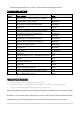
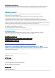
After wiring installation is complete, turn on the device by holding the power button for 2-4s until the power LED
illuminates. You may see the device progress through a series of start-up steps, indicated by different LEDs as
detailed below. This process typically takes 2 minutes but can take up to 20 minutes on first power-up.