
Getting Started Guide


4 | Rev. 0.4
Review this installation manual to become familiar with all installation procedures and electrical wiring
requirements prior to starting the installation. This installation guide has been prepared to provide you with
details necessary to complete the device installation.
Use of proper tools and testing equipment is required. Never use a grounding style test light. Use only aDigital
Multi Meter (DMM) to test wires in the vehicle.
Ensure that all wiring is protected from heat sources and sharp metal edges and is routed in suchmanner that it
will not get damaged or pinched when vehicle components and trim are reinstalled. Run newwiring along
factory harnesses and secure with quality cable zip-ties. Be sure to leave a “service loop” near thedevice,
enough slack in the wiring to allow working room and strain relief.
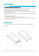
The device is NOT waterproof, never mount the device in the engine compartment. When mounting thedevice,
determine best possible location under the dash and make sure that the device will be securely attachedusing
self-tapping screws or cable zip-ties. Do not force or jam the device into tight places instead of mountingit.
When mounting the Device, do not obstruct any serviceable areas such as fuseboxes, etc. The device and
itswiring must be mounted away from any moving parts such as brake, gas, and clutch pedals and linkages.
Installation
*Identify correct wires
1. Remove any interior/under dash trim necessary to gain access to vehicle’s wiring as well as all areas
where interconnecting wire harnesses will need to be located.
2. Individually isolate any wires in the device’s harnesses that will not be used during installation.
3. It is strongly recommended to locate and connect constant power and ignition wires at the ignition key
switch connector behind ignition key cylinder or trace and connect at ignition switch wiring harness
running down steering column. (Note: If the ignition switch harness is not accessible,amperage restriction
exists, or the vehicle has an electronic starting system, constant power and ignitionconnections can be
made at the interior fuse box)
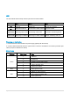
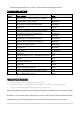
4. Use a multimeter and the color tables below to identify constant power and ignition wires.
5. The correct constant power wire will have battery voltage +12V (or +24V) present at all times, even when
theignition key is in off position or removed. Connect the device’s red wire here.
6. The correct ignition wire will have +12V (or +24V) present only when -- the key is in ON position,