
Users Manual


Automotive Module Series
AG525R-GL QuecOpen
Hardware Design
AG525R-GL_QuecOpen_Hardware_Design 23 / 104
1. Keep all RESERVED pins and unused pins unconnected.
2. GND pins should be connected to ground in the design.
3.3. Pin Description
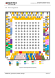
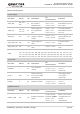
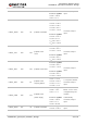
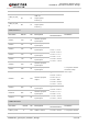
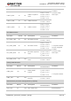
The following tables show the pin definition of the module and the alternate functions of multiplexing pins.
Table 3: I/O Parameters Definition
Type Description
AI Analog input
AO Analog output
B Bidirectional digital with CMOS input
DI Digital input
DO Digital output
H High level
IO Bidirectional
L Low level
OD Open drain
PD Pull down
PI Power input
PO Power output
PU Pull up
R Slew-rate limited
S Schmitt trigger input
NOTES