
EVB User Guide V1.0
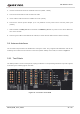
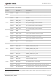
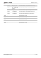
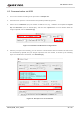
Table Of Contents
- Safety Information
- About the Document
- Contents
- Table Index
- Figure Index
- 1 Introduction
- 2 General Overview
- 3 Interface Application
- 3.1. Power Supply (J0202/J0601)
- 3.2. Switches, Button and Status Indicators
- 3.3. M.2 Interface (J0101)
- 3.4. USB Type-C Interface (J0601)
- 3.5. USB-TO-UART Interface (J0901/J0902)
- 3.6. (U)SIM Interfaces (J0701/J0702)
- 3.7. Audio Interfaces (J0801/J0802/J0803)
- 3.8 PCIe Interface to WLAN/Ethernet Module (J0501/J0502)
- 3.9. Antenna Interfaces
- 3.10. Test Points
- 4 Operation Procedures
- 5 Appendix References

5G Module Series
5G-M2_EVB_User_Guide 29 / 34
4.2. Communication via USB
1. Turn on the module according to the procedure in Chapter 4.1.
2. Install and then open the communication tool QCOM provided by Quectel.
3. Select correct “COM Port” (the port number of USB AT Port, e.g., “COM24” as exemplified in Figure
20) and “Baudrate” (such as 115200 bps), and then click “Open Port”. For more details about the
usage of QCOM, refer to document [2].
Figure 21: COM Port and Baudrate Configurations
4. After the port opens successfully, you can start the communication with the module via USB. Send
AT commands by QCOM, and you will get responses from the module, as shown by the following
figure. For detailed AT commands, see document [3].
Figure 22: Example of an AT Command