
EVB User Guide V1.0
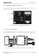
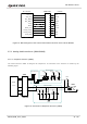
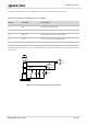
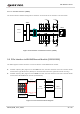
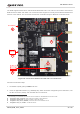
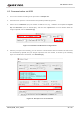
Table Of Contents
- Safety Information
- About the Document
- Contents
- Table Index
- Figure Index
- 1 Introduction
- 2 General Overview
- 3 Interface Application
- 3.1. Power Supply (J0202/J0601)
- 3.2. Switches, Button and Status Indicators
- 3.3. M.2 Interface (J0101)
- 3.4. USB Type-C Interface (J0601)
- 3.5. USB-TO-UART Interface (J0901/J0902)
- 3.6. (U)SIM Interfaces (J0701/J0702)
- 3.7. Audio Interfaces (J0801/J0802/J0803)
- 3.8 PCIe Interface to WLAN/Ethernet Module (J0501/J0502)
- 3.9. Antenna Interfaces
- 3.10. Test Points
- 4 Operation Procedures
- 5 Appendix References

5G Module Series
5G-M2_EVB_User_Guide 25 / 34
3. Insert the RTL8111H TE-A into the BTB connector (J0501, J0502).
4. Connect the EVB and PC with an Ethernet cable.
5. Insert a Micro-SIM card into the USIM1 connector (J0701).
6. Connect the AC-DC power adapter (5 V/ 3 A) between an AC power source and the power jack
(J0202).
7. Switch S0201 to PWR_ON side and S0101 to PWRKEY_ON side to power on the whole EVB and
turn on the module.
8. Until the green LED on RTL8111H TE-A blinks, it shows that the Ethernet PHY works normally.
3.9. Antenna Interfaces
The six antennas provided in the EVB kit are exactly the same. They support 600–6000 MHz and can be
randomly connected to the six antenna connectors (ANT0–ANT5) on the EVB, as shown in Figure 1.
3.10. Test Points
The EVB provides a series of test points, helping to obtain the corresponding waveform of specific signals,
as shown by the following figure and table.
1
2
3
4
5
6
7
8
10
9
1
2
3
4
5
1
2
3
4
5
3
2
1
3
2
1
3
2
1
3
2
1
1
2
3
4
5
5
4
3
2
1
1
2
Figure 19: Test Points of the EVB