
EVB User Guide V1.0
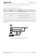
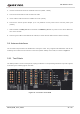
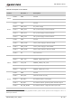
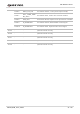
Table Of Contents
- Safety Information
- About the Document
- Contents
- Table Index
- Figure Index
- 1 Introduction
- 2 General Overview
- 3 Interface Application
- 3.1. Power Supply (J0202/J0601)
- 3.2. Switches, Button and Status Indicators
- 3.3. M.2 Interface (J0101)
- 3.4. USB Type-C Interface (J0601)
- 3.5. USB-TO-UART Interface (J0901/J0902)
- 3.6. (U)SIM Interfaces (J0701/J0702)
- 3.7. Audio Interfaces (J0801/J0802/J0803)
- 3.8 PCIe Interface to WLAN/Ethernet Module (J0501/J0502)
- 3.9. Antenna Interfaces
- 3.10. Test Points
- 4 Operation Procedures
- 5 Appendix References

5G Module Series
5G-M2_EVB_User_Guide 22 / 34
The table below illustrates the pin assignment and definition of the earphone connector.
Table 7: Pin Definition of Earphone Interface (J0801)
The following figure shows a reference design for the audio plug which matches the earphone connector
on the EVB.
2
1
MIC
GND
SW
SPK_R
SPK_L
3
4
32 Ω
32 Ω
Figure 15: Reference Design for the Audio Plug
Pin No.
Pin Name
Description
1
MIC
Microphone analog input
2
AGND
Analog ground
3
SPK_R
Right channel of stereo audio output
4
SPK_L
Left channel of stereo audio output
5, 6
NC
Not connected