
EVB User Guide V1.0
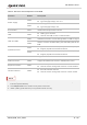
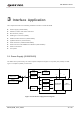
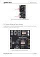
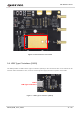
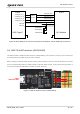
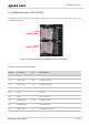
Table Of Contents
- Safety Information
- About the Document
- Contents
- Table Index
- Figure Index
- 1 Introduction
- 2 General Overview
- 3 Interface Application
- 3.1. Power Supply (J0202/J0601)
- 3.2. Switches, Button and Status Indicators
- 3.3. M.2 Interface (J0101)
- 3.4. USB Type-C Interface (J0601)
- 3.5. USB-TO-UART Interface (J0901/J0902)
- 3.6. (U)SIM Interfaces (J0701/J0702)
- 3.7. Audio Interfaces (J0801/J0802/J0803)
- 3.8 PCIe Interface to WLAN/Ethernet Module (J0501/J0502)
- 3.9. Antenna Interfaces
- 3.10. Test Points
- 4 Operation Procedures
- 5 Appendix References

5G Module Series
5G-M2_EVB_User_Guide 18 / 34
J0601 J0101
USB_DM
USB_DP
USB_SS_TX_P
USB_SS_TX_M
USB_SS_RX_P
USB_SS_RX_M
U0601
USB_DM
USB_DP
USB_SS_RX_P
USB_SS_RX_M
USB_SS_TX_P
USB_SS_TX_M
TP0101(DP)
0Ω
0Ω
HD3SS3220
M.2 Module
TP0102(DM)
TP0605(GND)
USB Type-C
Figure 8: Block Diagram of Connections Between the Module and the USB Type-C Interface
3.5. USB-TO-UART Interface (J0901/J0902)
The EVB provides a USB-TO-UART interface (J0901/J0902). This interface is used for Linux console and
converting debug log UART signal to USB 2.0 signal.
Before using the USB-TO-UART interface, DBG_RXD and DBG_TXD of the module should be connected
to the corresponding positions of J0902.2 (RXD_1V8) and J0902.3 (TXD_1V8) on the EVB respectively. A
connection example of RM500Q-GL module is shown as below.
J0901
USB-TO-UART
DBG_RXD
DBG_TXD
1
2
3
4
5
RM500Q-GL
J0902
Figure 9: USB-TO-UART Interface (J0901/J0902)