
EVB User Guide V1.0
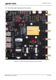
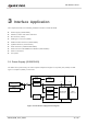
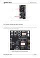
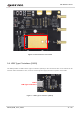
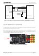
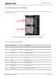
Table Of Contents
- Safety Information
- About the Document
- Contents
- Table Index
- Figure Index
- 1 Introduction
- 2 General Overview
- 3 Interface Application
- 3.1. Power Supply (J0202/J0601)
- 3.2. Switches, Button and Status Indicators
- 3.3. M.2 Interface (J0101)
- 3.4. USB Type-C Interface (J0601)
- 3.5. USB-TO-UART Interface (J0901/J0902)
- 3.6. (U)SIM Interfaces (J0701/J0702)
- 3.7. Audio Interfaces (J0801/J0802/J0803)
- 3.8 PCIe Interface to WLAN/Ethernet Module (J0501/J0502)
- 3.9. Antenna Interfaces
- 3.10. Test Points
- 4 Operation Procedures
- 5 Appendix References

5G Module Series
5G-M2_EVB_User_Guide 15 / 34
J0202
5V Power Supply
J0601
USB Power Supply
Figure 4: EVB Power Supply Interfaces (J0202/J0601)
3.2. Switches, Button and Status Indicators
The EVB provides four switches (S0101/S0201/S0301/S1101), one button (S0102), and two indicators
(D0107/D0108), as shown in the following figure.
LOW level side
HIGH level side
LOW level side
HIGH level side
Figure 5: Switches, Button and Status Indicators