LMU-3x40 CalAmp LMU-3x40 Training Guide
LMU-3x40 Training Guide Revision & Date 1.6 – 03/24/2021 CalAmp reserves the rights to these documents and any information contained therein. Reproduction use or disclosure to third parties without express permission is strictly prohibited. ©2021 CalAmp Contents 1. Scope ........................................................................................................................................................ 5 Platform Introduction ...........................................................
LMU-3x40 Training Guide Revision & Date 1.6 – 03/24/2021 5.3 PEG2 TAG Definitions ......................................................................................................................... 19 5.4 Multiple Modifiers ............................................................................................................................. 20 5.5 PEG1 -> PEG2 Conversion ..................................................................................................................
LMU-3x40 Training Guide Revision & Date 1.6 – 03/24/2021 7.2 GPS Verification.................................................................................................................................... 33 7.3 Inbound Verification ............................................................................................................................ 34 7.4 Verification via SMS .......................................................................................................................
LMU-3x40 Training Guide Revision & Date 1.6 – 03/24/2021 1. Scope This document provides an overview of CalAmp’s Telematics EdgeCore platform, referred as EdgeCore hereafter, the associated products, its highlights and major features. It also serves as a training manual on ‘how-to’ get started with an EdgeCore device (e.g. LMU-3040). Lastly, this document serves to describe the major differences between EdgeCore and the LMU32 predecessor platforms.
Revision & Date 1.6 – 03/24/2021 LMU-3x40 Training Guide The design and architecture of this software platform achieve the intended benefits by following these principles: 1. Modularity and compactness of system. One module envelops one concept and/or task. 2. Commonality across modules to allow more efficient methods to understand code across different platforms and developers. 3.
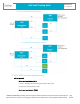
LMU-3x40 Training Guide Revision & Date 1.6 – 03/24/2021 1.4.1LMU-3040 Hardware Architecture: 1.4.2 LMU-3240 Hardware Architecture: 2. LMU-3040 Hardware Specifications Cellular/Network North American Variant I (ATT): LTE Cat 1: 1900 (B2)/AWS 1700 (B4)/850 (B5)/700 (B12) MHz HSPA/UMTS+: 850 (V)/1900 (II) MHz North American Variant II (VZW): COMPANY CONFIDENTIAL: CalAmp reserves all rights to these documents and any information contained therein.
LMU-3x40 Training Guide Revision & Date 1.
LMU-3x40 Training Guide Revision & Date 1.
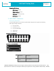
LMU-3x40 Training Guide Revision & Date 1.6 – 03/24/2021 Connectors/SIM Access GPS Antenna Internal Cellular Antenna Internal SIM Access Internal (4FF SIM) BLE Antenna Internal 3. LMU-3040™ Connectors 3.1 Primary Connector The LMU-3040 equips a 16-Pin J1962 Compliant OBD-II Plug that also supports the following OBD-II physical layer interfaces: 1. ISO 15765 CAN 2. ISO 9141-2 K-Line 3. ISO 14230 KWP2000] 4. J1850 PWM 5.
LMU-3x40 Training Guide 2 3 Bus+ Line Make/Model Specific SAE-J1850 PWM and SAE-1850 VPW Vendor Option 4 Chassis Ground Ground 5 Signal Ground Ground 6 Can High ISO 15765-4 and SAE-J2284 7 K line ISO 9141-2 and ISO 14230-4 8 Make/Model Specific 10 Bus- Line Revision & Date 1.6 – 03/24/2021 Vendor Option SAE-J1850 PWM and SAE-1850 VPW 11 Make/Model Specific 14 Can Low ISO 15765-4 and SAE-J2284 15 L line ISO 9141-2 and ISO 14230-4 16 Battery Power Vendor Option Power 4.
LMU-3x40 Training Guide Revision & Date 1.6 – 03/24/2021 4.1 The Basics SIM Card The LMU-3x40 product line is the first LMU to use a 4FF (nano) SIM card, as opposed to the common 2FF (mini) SIM card that is required for other LMUs. SSH Client LMU-3x40 has a micro USB port in place of a RS-232/TTL UART serial interface. To physically access the device through the USB connector, the device utilizes a Secure Shell protocol or “SSH”. A SSH client (e.g. Putty) is required to login and access the device.
LMU-3x40 Training Guide Revision & Date 1.6 – 03/24/2021 File Transfer LMU-3x40 requires Secure Copy Protocol (SCP) to transfer files from a laptop or PC onto the device. A common SCP tool to perform this task with Windows is the WIN SCP. SCP only allows for transfer of a file. Programming or flashing of a certain file type is a different step as explained in Section 4.8. 4.2 SSH Credentials A set of default credentials is required for access to the device.
LMU-3x40 Training Guide Revision & Date 1.6 – 03/24/2021 4.4 Command Line Interface (CLI) From the Linux Console you can send ‘AT’ commands to retrieve traditional LMU Application responses. The format of this command is the following: • • atcmd_cli atcmd “AT command” Quotes are required Below is an example of how to send ‘ATIC’ directly from Linux: COMPANY CONFIDENTIAL: CalAmp reserves all rights to these documents and any information contained therein.
Revision & Date 1.6 – 03/24/2021 LMU-3x40 Training Guide 4.5 Log File Engineering and LMU logs can be found in the Linux file system. You can find the most recent log file in a specific /var/log/ directory, in a file named messages If you would like to view new information that is written to this log file, Linux offers a way to do this through the command line. • Enter: tail –F /var/log/messages This command will open the messages file and display the latest written lines of the file.
LMU-3x40 Training Guide Revision & Date 1.6 – 03/24/2021 All file sizes are subject to change. Important Note: Data plans may be impacted due to the larger size of FW delta files. 4.8 Software & Script Updates All of these files can be updated Over-The-Air if subscribed to Calamp’s Device Management Service (PULS). These files can also be updated with physical access to the device as well. Below are the steps and options below: 1. Transfer Firmware/Script (e.g.
LMU-3x40 Training Guide • Revision & Date 1.6 – 03/24/2021 In-line comments 5.2 PEG2 File In next generation devices supporting PEG2, the file containing the PEG script and the configurations parameters has an updated format.
Revision & Date 1.6 – 03/24/2021 LMU-3x40 Training Guide Configuration Parameters TAG Definition !CP: Following this tag, this is where all the Config Parameters start until the PEG2 script section starts or the EOF is detected. Important Notes: • Config Parameters use the same format as in a PEG1 file • Config Parameters are still a union of the file contents and what already resides on the target device Example !CP: 256,0,00 256,1,01 256,2,00 256,3,00 257,0,15D4 259,3,00 260,0,00 260,1,00 ....
LMU-3x40 Training Guide Revision & Date 1.6 – 03/24/2021 End of File (EOF) and CRC TAG Definition !EOF: End-of-file marker (this tag) must be included !CRC: Following EOF marker, a 2-byte binary CRC value must be appended to validate integrity of file during transit. This is needed for OTA and Serial transfers Example ... L514014;T18,35;A112,0,0 L514015;T15,0;A112,0,0 L514250;T0,0;A0,0 !EOF: %P Important Note: If !SIG or !CRC is incorrect, PULS will re-calculate upon upload.
Revision & Date 1.6 – 03/24/2021 LMU-3x40 Training Guide : Comm ent The comment tag ‘:’ is immediately followed by free text and is only terminated by the end-of-line delimiter () + OR Boolean operator that combines result with next Condition results using ‘OR’ operation ^ AND Boolean operator that combines result with next Condition results using ‘AND’ operation ! NOT Boolean operator that inverts results of following Condition or previous Boolean state depending on placement.
LMU-3x40 Training Guide Revision & Date 1.6 – 03/24/2021 PEG1 single modifier mapping: Upper 4 bits = Source, Lower 4 bits = Destination Example: “I want to copy Accumulator 10 into Accumulator 22 every second” PEG1 PEG2 Example Not possible using PEG Action 103 (Copy Accum). Possible with this PEG2 line: Limited to 4 bits (accum 0-15) T18,5;A103,10,22 Using PEG Action 124 (Select Dest.) & 125 (Copy to Dest.): Possible with one PEG2 line: T18,5;A103,10,22 120500007C160000 120500007D0A0000 5.
LMU-3x40 Training Guide Revision & Date 1.6 – 03/24/2021 Step2: Convert an LMU-3x40 PEG1 script file into an LMU-3x40 PEG2 script file o o o Load 3x40 PEG1 script to convert (from Step 1) Select “Export” -> “PEG2 format (*.pg2)” selection Press OK and Save File Note: A more detailed step-by-step PEG1->PEG2 conversion user guide can be made available 5.6 PEG2 Native Editor The latest LMU Manager also offers a way to create or edit PEG2 files natively, without requiring a PEG1 to PEG2 conversion.
LMU-3x40 Training Guide Revision & Date 1.6 – 03/24/2021 PEG2 Readable Text To switch from PEG2 ASCII to readable text, you can toggle the blue cross bar icon on top left. Single Line Editor Double click on any line to open the Single Line Editor screen to add, edit, delete or insert a PEG2 COMPANY CONFIDENTIAL: CalAmp reserves all rights to these documents and any information contained therein. Page Reproduction use or disclosure to third parties without express permission is strictly prohibited.
LMU-3x40 Training Guide Revision & Date 1.6 – 03/24/2021 6. LMU32 vs EdgeCore Platform Differences 6.1 I/O Mapping & Wake-Up Sources Inputs 0-4 and Input 14 are mapped the same on the LMU-3040 as they are on the LMU-3030. However, on the LMU-3x40 platform, these same enumerated inputs are NOT used as wake-up sources. Monitoring the status of these inputs within a PEG Script is the same as on the LMU-3040, however, to set these inputs as a wake-up source requires setting a different input in param 1029.
Revision & Date 1.
LMU-3x40 Training Guide Revision & Date 1.6 – 03/24/2021 For example: if a fleet of 100 units is on 3 different firmware versions (v1.10.1, 1.10.4, and 1.11.4), to get all 100 units on to the same target firmware (1.12.0) requires 3 unique delta images: • • • Delta Image1: 1.10.1 -> 1.12.0 Delta Image2: 1.10.4 -> 1.12.0 Delta Image3: 1.11.4 -> 1.12.0 If there is no Delta Image available to get to the target firmware directly, a multi-step update would be required.
LMU-3x40 Training Guide Revision & Date 1.6 – 03/24/2021 6.4 PEG2 “Lines” As stated in section 5.1.3 above, PEG2 lines are no longer considered “parameters”. A PEG2 “line” is only a virtual line, but in reality they are not enumerated the same way as in a PEG1 script. The Script (!SCR) section of a PEG2 file is one whole section that requires either deleting or updating the whole section at once. No individual “line” can be updated.
Revision & Date 1.6 – 03/24/2021 LMU-3x40 Training Guide Peg Action 144 2 - Save log files in a tar ball in /data/backup/ and upload the file. This is good for timer or event based log saving. 6.7 Modem/GPS Reset The LMU-3x40 hardware architecture does not support rebooting the modem and/or GPS, since both are on the same chip, they both use the same power rail. A complete system reboot is required to reboot either function. This does not apply to the BLE and Wi-Fi functions. 6.
Revision & Date 1.6 – 03/24/2021 LMU-3x40 Training Guide PEG Accumulators PEG Timers PEG Condition Groups PEG TimeDate Masks PEG Event Lines/Pages PEG Zones LMU-3030 32 32 8 8 500/2 32 LMU-3040 254 254 32 10 Peg2 Script 32 LMU-3240 254 254 32 10 Peg2 Script 32 6.11 GPS Some of the notable differences between GPS operation are indicated inthe following table.
LMU-3x40 Training Guide Revision & Date 1.6 – 03/24/2021 6.14 Version String in ID Reports The EdgeCore platform sends and displays the version string in a different format. ID Reports: The firmware version of the LMU-3x40, can be obtained from the LMDirect ID Report, Extension String field. In that field, there is a new Key-Value pair in the “LMUAPP” extension string. See the definition below.
Revision & Date 1.6 – 03/24/2021 LMU-3x40 Training Guide 6.16 Status LEDs The LMU-3040 and LMU-3240 have single dual color LED on the board, green and red. The device firmware has individual controls for each color and can program each color individually or together to generate green, red or amber. Currently the devices only display a solid amber light to indicate if the device is powered on or off. There is no blinking pattern defined to indicate GPS/Cell status or Vehicle Installation status.
LMU-3x40 Training Guide Revision & Date 1.6 – 03/24/2021 7. Installation Verification In many cases it is desirable to verify that an installed LMU-3040™ is working properly. That is, installers should verify that the GPS and communications functions of the LMU-3040™ are working properly before departing the installation site. In more robust cases, some key configuration settings such as the Inbound Address and URL should also be verified.
LMU-3x40 Training Guide Connection : Yes RSSI : -97 dBm BER : Channel Cell ID 99 : : Revision & Date 1.6 – 03/24/2021 737 3441 Base Station ID : 40 Local Area Code : 31003 Network Code : 410 Country Code : 310 IMEI (Modem S/N): 351802055396182 IMSI (SIM ID) : 310410202524377 ICC-ID (SIM S/N): 89014102212025243778 Phone Number : GPRS APN : ISP.CINGULAR Maint. Server : maint.vehiclelocation.com(216.177.93.246):20500 Inbound Server : (0.0.0.
LMU-3x40 Training Guide Revision & Date 1.6 – 03/24/2021 Lat=3304713, Lon=-11727730, Alt=0 Hdg=113 Spd=0 3D-RTIME HDOP=130 nSats=7 Installers are looking for the 3D-RTIME setting along with a valid Lat, Long pair (i.e. something other than 0). If the GPS receiver does not have a valid lock within 2-3 minutes, for further troubleshooting, installers should contact CalAmp Support (productsupport@CalAmp.com) 7.
LMU-3x40 Training Guide Revision & Date 1.6 – 03/24/2021 The backend monitor must then be contacted to confirm that they received an Event Report with Event Code 255. Assuming that all three sections have passed, the installation can be considered to be complete. 7.4 Verification via SMS The current Comm, GPS and Inbound status of a LMU can be obtained via SMS provided you have access to an SMS capable phone or PDA.
LMU-3x40 Training Guide Revision & Date 1.6 – 03/24/2021 If the character ‘D’ is present, it indicates the LMU had a data session established when it responded to the status request. For the 8-Bit product line an upper case ‘D’ indicates both the Inbound and Maintenance sockets are ready. The lower case ‘d’ indicates that only the Maintenance socket is ready. A ‘.’ indicates no sockets are ready. o [./a/A]: This field indicates if the LMU has received an Acknowledgement from the Inbound server.
Revision & Date 1.6 – 03/24/2021 LMU-3x40 Training Guide o : INP: This field details the current state of each of the LMU’s discreet inputs. This field is always 8 characters long. The left most character represents the state of input 7 where the right most represents the state of input 0 (i.e. the ignition). A value of 1 indicates the input is currently in the high state. A value of 0 indicates it is currently in the low state.
LMU-3x40 Training Guide Revision & Date 1.6 – 03/24/2021 8. Regulatory Information Human Exposure Compliance Statement Pursuant to 47 CFR § 24.52 of the FCC Rules and Regulations, personal communications services (PCS) equipment is subject to the radio frequency radiation exposure requirements specified in § 1.1307(b), § 2.1091 and § 2.1093, as appropriate. CalAmp Wireless Networks Inc.
LMU-3x40 Training Guide Revision & Date 1.6 – 03/24/2021 Note: This equipment has been tested and found to comply with the limits for a Class B digital device, pursuant to part 15 of the FCC Rules. These limits are designed to provide reasonable protection against harmful interference in a residential installation. This equipment generates, uses and can radiate radio frequency energy and, if not installed and used in accordance with the instructions, may cause harmful interference to radio communications.
LMU-3x40 Training Guide Revision & Date 1.6 – 03/24/2021 Déclaration d'exposition aux radiations: Cet équipement est conforme aux limites d'exposition aux rayonnements IC établies pour un environnement non contrôl é. Cet équipement doit être installé et utilisé avec un minimum de 20 cm de distance entre la source de rayonnement et votre corps.