
Product Info

Smart Module Series
SC200R Series Hardware Design
SC200R_Series_Hardware_Design 56 / 125
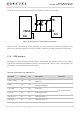
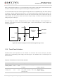
3.16. ADC Interface
SC200R series module supports one analog-to-digital converter (ADC) interface. The ADC interface
supports resolution of up to 15 bits. The pin definition is shown below.
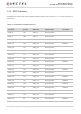
Table 20: Pin Definition of ADC Interface
3.17. Motor Drive Interface
The pin definition of the motor drive interface is listed below.
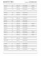
Table 21: Pin Definition of Motor Drive Interface
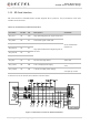
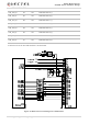
UART5_CTS 36 DO SPI5 chip select Can be multiplexed into SPI5_CS
GPIO_22 117 DO SPI6 chip select Can be multiplexed into SPI6_CS
GPIO_23 116 DO SPI6 clock Can be multiplexed into SPI6_CLK
GPIO_20 119 DO SPI6 data output Can be multiplexed into SPI6_MOSI
GPIO_21 118 DI SPI6 data input Can be multiplexed into SPI6_MISO
GPIO_87 105 DO SPI7 chip select Can be multiplexed into SPI7_CS
GPIO_85 265 DO SPI7 data output Can be multiplexed into SPI7_MOSI
GPIO_88 264 DO SPI7 clock Can be multiplexed into SPI7_CLK
GPIO_86 239 DI SPI7 data input Can be multiplexed into SPI7_MISO
Pin Name Pin No.
I/O Description Comment
ADC 128 AI Generic ADC The maximum input voltage is 1.7 V.
Pin Name Pin No. I/O Description Comment
VIB_DRV_N
28 PO Motor drive Connect it to the negative pole of the motor.