
Product Info

Smart Module Series
SC200R Series Hardware Design
SC200R_Series_Hardware_Design 51 / 125
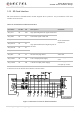
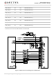
SD_LDO11 is the power supply for the SD card and can provide up to 800 mA output current. Due to the
high output current, it is recommended that the trace width should be at least 0.8 mm. In order to ensure
stability of output current, add a 4.7 μF and a 33 pF capacitor in parallel near the SD card connector.
SD_CMD, SD_CLK, SD_DATA0, SD_DATA1, SD_DATA2, and SD_DATA3 are all high-speed signal lines.
In PCB design, control the characteristic impedance of them to 50 Ω, and do not cross them with other
traces. It is recommended to route the traces on the inner layer of PCB and keep them of the same length.
Additionally, SD_CLK needs separate ground shielding.
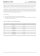
Layout guidelines:
Control the impedance to 50 Ω ±10 % and add ground shielding.
The total trace length difference between SD_CLK and other signal traces like SD_CMD and
SD_DATA should not exceed 1 mm.
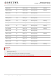
Table 16: SD Card Trace Length Inside the Module
Pin No. Signal Length (mm)
39 SD_CLK 21.50
40 SD_CMD 21.40
41 SD_DATA0 21.45
42 SD_DATA1 21.60
43 SD_DATA2 21.40
44 SD_DATA3 21.35