
Product Info

Smart Module Series
SC200R Series Hardware Design
SC200R_Series_Hardware_Design 47 / 125
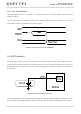
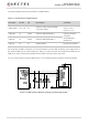
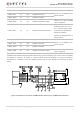
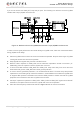
The following figure is an example of connection between the module and PC. It is recommended to add
a level translator and an RS-232 level translator chip between the module and PC. The following figure
shows the reference design.
Figure 14: RS-232 Level Match Circuit (for UART5)
UART2 and UART1 are similar to UART5. For the reference design, refer to that of UART5.
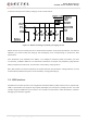
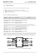
3.11. (U)SIM Interfaces
SC200R series module provides two (U)SIM interfaces that meet ETSI and IMT-2000 requirements. Dual
SIM Dual Standby is supported by default. Either 1.8 V or 2.95 V (U)SIM card is supported, and the
(U)SIM card is powered by the internal power supply of the module.
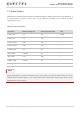
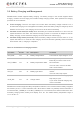
Table 14: Pin Definition of (U)SIM Interfaces
Pin Name Pin No.
I/O Description Comment
USIM2_DET 17 DI (U)SIM2 card hot-plug detect
Active low.
Externally pull it up to 1.8 V.
If it is not used, keep it open.
This function is disabled by
default via software.
Cannot be multiplexed into a
generic GPIO.
NOTE