
Product Info

Smart Module Series
SC200R Series Hardware Design
SC200R_Series_Hardware_Design 44 / 125
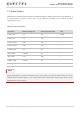
The following table shows the pin definition of USB interface.
Table 11: Pin Definition of USB Interface
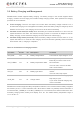
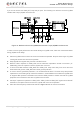
For the design of USB 2.0 interface, it is recommended to connect USB_ID directly to the USB_ID pin of
the external USB port for USB ID detection. When you insert a device into the external USB port, the
USB_ID pin of the module will be pulled down to make the module enter host mode.
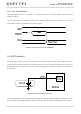
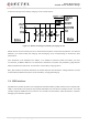
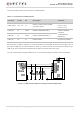
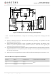
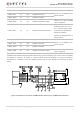
You can choose either to support USB OTG or not. The following figures show the reference designs.
Figure 11: USB Interface Reference Design (OTG Not Supported)
Pin Name Pin No. I/O Description Comment
USB_VBUS 141, 142 PI
USB 5 V power input and USB
connection detect
Vmax = 6.2 V
Vmin = 4.35 V
Vnorm = 5.0 V
USB_DM 13 AI/AO USB 2.0 differential data (-)
USB 2.0 standard
compliant.
90 Ω differential
impedance.
USB_DP 14 AI/AO USB 2.0 differential data (+)
USB_ID 16 AI USB ID detect High level by default.