
Product Info

Smart Module Series
SC200R Series Hardware Design
SC200R_Series_Hardware_Design 36 / 125
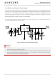
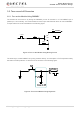
To decrease voltage drop, use a bypass capacitor of about 100 µF with low ESR (ESR = 0.7 Ω), and
reserve a multi-layer ceramic chip capacitor (MLCC) array due to its ultra-low ESR. It is recommended to
use three ceramic capacitors (100 nF, 33 pF, 10 pF) to compose the MLCC array and place these
capacitors close to VBAT_BB/VBAT_RF pins. Additionally, add a 4.7 µF capacitor in parallel. The main
power supply from an external application has to be a single voltage source and can be expanded to two
sub paths with star structure. The width of VBAT trace should be no less than 3 mm. In principle, the
longer the VBAT trace is, the wider it should be.
In addition, in order to get a stable power source, it is suggested to use a TVS and place it as close to the
VBAT_BB/VBAT_RF pins as possible to enhance surge protection. The following figure shows the star
structure of the power supply.
Figure 3: Star Structure of the Power Supply