
Service Guide
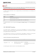


Table Of Contents
- Safety Information
- About the Document
- Contents
- Contents
- Table Index
- Figure Index
- 1 Introduction
- 2 Product Overview
- 3 Application Interfaces
- 3.1. General Description
- 3.2. Pin Assignment
- 3.3. Pin Description
- 3.4. Operating Modes
- 3.5. Power Saving
- 3.6. Power Supply
- 3.7. Turn on/Turn off/Reset
- 3.8. (U)SIM Interfaces
- 3.9. USB Interface
- 3.10. UART Interfaces
- 3.11. SPI Interface
- 3.12. I2C Interfaces
- 3.13. PCM Interface
- 3.14. Analog Audio Interfaces
- 3.15. LCD Interface
- 3.16. Matrix Keyboard Interface
- 3.17. SD Card Interface
- 3.18. WLAN Application Interface*
- 3.19. ADC Interfaces
- 3.20. Network Status Indication
- 3.21. STATUS
- 3.22. Behaviors of MAIN_RI
- 3.23. USB_BOOT Interface
- 4 Antenna Interfaces
- 5 Electrical Characteristics, Radio and Reliability
- 6 Mechanical Information
- 7 Storage, Manufacturing & Packaging
- 8 Appendix References

LTE Standard Module Series
EC200U_Series_Hardware_Design 61 / 94
4.1.3. Reference Design of RF Antenna Interfaces
A reference design of ANT_MAIN and ANT_BT/WIFI_SCAN is shown as below. A π-type matching circuit
should be reserved for better RF performance. The capacitors are not mounted by default.
ANT_MAIN
R1 0R
C1
Module
Main
antenna
NM
C2
NM
R2 0R
C3
Wi-Fi Scan/
Bluetooth
antenna
NM
C4
NM
ANT_BT/WIFI
_SCAN
Figure 29: Reference Circuit of RF Antenna Interfaces
4.2. GNSS Antenna Interface
The following tables list the pin definition and frequency characteristics of the GNSS antenna interface
respectively.
Table 37: Pin Definition of GNSS Antenna Interface
1. In order to improve the receiving sensitivity, it is necessary to ensure the proper distance between
the main antenna and Wi-Fi Scan/Bluetooth receiving antenna.
2. Place the π-type matching components (R1 & C1 & C2 and R2 & C3 & C4) as close to the antenna
as possible.
Pin Name
Pin No.
I/O
Description
Comment
NOTE