
Service Guide

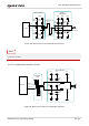


Table Of Contents
- Safety Information
- About the Document
- Contents
- Contents
- Table Index
- Figure Index
- 1 Introduction
- 2 Product Overview
- 3 Application Interfaces
- 3.1. General Description
- 3.2. Pin Assignment
- 3.3. Pin Description
- 3.4. Operating Modes
- 3.5. Power Saving
- 3.6. Power Supply
- 3.7. Turn on/Turn off/Reset
- 3.8. (U)SIM Interfaces
- 3.9. USB Interface
- 3.10. UART Interfaces
- 3.11. SPI Interface
- 3.12. I2C Interfaces
- 3.13. PCM Interface
- 3.14. Analog Audio Interfaces
- 3.15. LCD Interface
- 3.16. Matrix Keyboard Interface
- 3.17. SD Card Interface
- 3.18. WLAN Application Interface*
- 3.19. ADC Interfaces
- 3.20. Network Status Indication
- 3.21. STATUS
- 3.22. Behaviors of MAIN_RI
- 3.23. USB_BOOT Interface
- 4 Antenna Interfaces
- 5 Electrical Characteristics, Radio and Reliability
- 6 Mechanical Information
- 7 Storage, Manufacturing & Packaging
- 8 Appendix References

LTE Standard Module Series
EC200U_Series_Hardware_Design 55 / 94
3.21. STATUS
The STATUS pin is an output for module’s operation status indication. When the module is turned on
normally, the STATUS outputs high level.
Table 30: Pin Definition of STATUS
A reference circuit is shown in the following figure.
4.7K
47K
VBAT
2.2K
Module
STATUS
Figure 27: Reference Circuit of STATUS
3.22. Behaviors of MAIN_RI
AT+QCFG="risignaltype","physical" can be used to configure MAIN_RI behaviors.
No matter on which port a URC is presented, the URC will trigger the behavior of MAIN_RI pin.
Pin Name
Pin No.
I/O
Description
Comment
STATUS
61
DO
Indicate the module's operation status
1.8 V power domain.
If unused, keep it open.
The STATUS cannot be used as the indication of power-down state when VBAT doesn’t supply power to
the module.
NOTE