
Service Guide
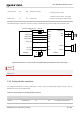

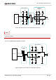


Table Of Contents
- Safety Information
- About the Document
- Contents
- Contents
- Table Index
- Figure Index
- 1 Introduction
- 2 Product Overview
- 3 Application Interfaces
- 3.1. General Description
- 3.2. Pin Assignment
- 3.3. Pin Description
- 3.4. Operating Modes
- 3.5. Power Saving
- 3.6. Power Supply
- 3.7. Turn on/Turn off/Reset
- 3.8. (U)SIM Interfaces
- 3.9. USB Interface
- 3.10. UART Interfaces
- 3.11. SPI Interface
- 3.12. I2C Interfaces
- 3.13. PCM Interface
- 3.14. Analog Audio Interfaces
- 3.15. LCD Interface
- 3.16. Matrix Keyboard Interface
- 3.17. SD Card Interface
- 3.18. WLAN Application Interface*
- 3.19. ADC Interfaces
- 3.20. Network Status Indication
- 3.21. STATUS
- 3.22. Behaviors of MAIN_RI
- 3.23. USB_BOOT Interface
- 4 Antenna Interfaces
- 5 Electrical Characteristics, Radio and Reliability
- 6 Mechanical Information
- 7 Storage, Manufacturing & Packaging
- 8 Appendix References

LTE Standard Module Series
EC200U_Series_Hardware_Design 54 / 94
Table 28: Pin Definition of Network Connection Status/Activity Indicator
Table 29: Working State of Network Connection Status/Activity Indicator
A reference circuit is shown in the following figure.
4.7K
47K
VBAT
2.2K
Module
Network
Indicator
Figure 26: Reference Circuit of Network Indicator
Pin Name
Pin No.
I/O
Description
Comment
NET_MODE
5
DO
Indicate the module's network activity
status
1.8 V power domain.
If unused, keep them
open.
NET_STATUS
6
DO
Indicate the module's network
registration mode
Pin Name
Logic Level Changes
Network Status
NET_STATUS
Always high
Registered on LTE network
Always low
Others
NET_MODE
Flicker slowly (200 ms high/1800 ms low)
Network searching
Flicker quickly (234 ms high/266 ms low)
Idle
Flicker rapidly (62 ms high/63 ms low)
Data transfer is ongoing
Always high
Voice calling