
Service Guide

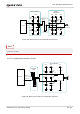


Table Of Contents
- Safety Information
- About the Document
- Contents
- Contents
- Table Index
- Figure Index
- 1 Introduction
- 2 Product Overview
- 3 Application Interfaces
- 3.1. General Description
- 3.2. Pin Assignment
- 3.3. Pin Description
- 3.4. Operating Modes
- 3.5. Power Saving
- 3.6. Power Supply
- 3.7. Turn on/Turn off/Reset
- 3.8. (U)SIM Interfaces
- 3.9. USB Interface
- 3.10. UART Interfaces
- 3.11. SPI Interface
- 3.12. I2C Interfaces
- 3.13. PCM Interface
- 3.14. Analog Audio Interfaces
- 3.15. LCD Interface
- 3.16. Matrix Keyboard Interface
- 3.17. SD Card Interface
- 3.18. WLAN Application Interface*
- 3.19. ADC Interfaces
- 3.20. Network Status Indication
- 3.21. STATUS
- 3.22. Behaviors of MAIN_RI
- 3.23. USB_BOOT Interface
- 4 Antenna Interfaces
- 5 Electrical Characteristics, Radio and Reliability
- 6 Mechanical Information
- 7 Storage, Manufacturing & Packaging
- 8 Appendix References

LTE Standard Module Series
EC200U_Series_Hardware_Design 50 / 94
3.17. SD Card Interface
The module supports SDIO 2.0 interface for SD card.
Table 24: Pin Definition of SD Card Interface
The following figure shows a reference design of SD card interface.
it can be used as KEYIN0
after startup.
KEYIN1
78
DI
Matrix keyboard input1
1.8 V power domain.
If unused, keep it open. The
KEYIN1 cannot be pulled up
before startup.
KEYIN2
79
DI
Matrix keyboard input2
1.8 V power domain.
If unused, keep them open.
KEYIN3
80
DI
Matrix keyboard input3
KEYOUT0
83
DO
Matrix keyboard output0
KEYOUT1
84
DO
Matrix keyboard output1
KEYOUT2
113
DO
Matrix keyboard output2
KEYOUT3
114
DO
Matrix keyboard output3
Pin Name
Pin No.
I/O
Description
Comment
SD_DET
23
DI
SD card detect
1.8 V power domain.
If unused, keep it open.
SDIO1_DATA3
28
DIO
SDIO data bit 3
1.8/3.2V power domain.
If unused, keep them open.
SDIO1_DATA2
29
DIO
SDIO data bit 2
SDIO1_DATA1
30
DIO
SDIO data bit 1
SDIO1_DATA0
31
DIO
SDIO data bit 0
SDIO1_CLK
32
DO
SDIO clock
SDIO1_CMD
33
DIO
SDIO command
SDIO1_VDD
34
PO
SDIO power supply