
Service Guide

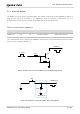


Table Of Contents
- Safety Information
- About the Document
- Contents
- Contents
- Table Index
- Figure Index
- 1 Introduction
- 2 Product Overview
- 3 Application Interfaces
- 3.1. General Description
- 3.2. Pin Assignment
- 3.3. Pin Description
- 3.4. Operating Modes
- 3.5. Power Saving
- 3.6. Power Supply
- 3.7. Turn on/Turn off/Reset
- 3.8. (U)SIM Interfaces
- 3.9. USB Interface
- 3.10. UART Interfaces
- 3.11. SPI Interface
- 3.12. I2C Interfaces
- 3.13. PCM Interface
- 3.14. Analog Audio Interfaces
- 3.15. LCD Interface
- 3.16. Matrix Keyboard Interface
- 3.17. SD Card Interface
- 3.18. WLAN Application Interface*
- 3.19. ADC Interfaces
- 3.20. Network Status Indication
- 3.21. STATUS
- 3.22. Behaviors of MAIN_RI
- 3.23. USB_BOOT Interface
- 4 Antenna Interfaces
- 5 Electrical Characteristics, Radio and Reliability
- 6 Mechanical Information
- 7 Storage, Manufacturing & Packaging
- 8 Appendix References

LTE Standard Module Series
EC200U_Series_Hardware_Design 44 / 94
MCU/ARM
TXD
RXD
VDD_EXT
10K
VCC_MCU
4.7K
10K
VDD_EXT
MAIN_TXD
MAIN_RXD
MAIN_RTS
MAIN_CTS
MAIN_DTR
MAIN_RI
RTS
CTS
GND
GPIO MAIN_DCD
Module
GPIO
EINT
VDD_EXT
4.7K
GND
1 nF
1 nF
Figure 21: Reference Circuit with Transistor Circuit
1. Triode level transistor circuit solution is not suitable for applications with baud rates exceeding 460
kbps.
2. Please note that the module CTS is connected to the host CTS, and the module RTS is connected
to the host RTS.
3.11. SPI Interface
The SPI interface of EC200U series module only supports master mode. It allows the full duplex
synchronous communication between module and peripherals. Its working voltage is 1.8 V, and the
maximum clock frequency is 25 MHz. If a universal 4-wire SPI interface is used to connect to Nor Flash, it
provides the basic Flash operation including reading, writing and erasing, and does not support the file
system.
Table 18: Pin Definition of SPI interface
Pin Name
Pin No.
I/O
Description
Comment
SPI_CS
37
DO
SPI chip select
If you use a module model
NOTE