
Service Guide

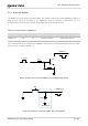


Table Of Contents
- Safety Information
- About the Document
- Contents
- Contents
- Table Index
- Figure Index
- 1 Introduction
- 2 Product Overview
- 3 Application Interfaces
- 3.1. General Description
- 3.2. Pin Assignment
- 3.3. Pin Description
- 3.4. Operating Modes
- 3.5. Power Saving
- 3.6. Power Supply
- 3.7. Turn on/Turn off/Reset
- 3.8. (U)SIM Interfaces
- 3.9. USB Interface
- 3.10. UART Interfaces
- 3.11. SPI Interface
- 3.12. I2C Interfaces
- 3.13. PCM Interface
- 3.14. Analog Audio Interfaces
- 3.15. LCD Interface
- 3.16. Matrix Keyboard Interface
- 3.17. SD Card Interface
- 3.18. WLAN Application Interface*
- 3.19. ADC Interfaces
- 3.20. Network Status Indication
- 3.21. STATUS
- 3.22. Behaviors of MAIN_RI
- 3.23. USB_BOOT Interface
- 4 Antenna Interfaces
- 5 Electrical Characteristics, Radio and Reliability
- 6 Mechanical Information
- 7 Storage, Manufacturing & Packaging
- 8 Appendix References

LTE Standard Module Series
EC200U_Series_Hardware_Design 38 / 94
The timing of resetting module is illustrated in the following figure.
V
IL
≤ 0.5 V
VBAT
Module
Status
Running
RESET_N
Baseband restart
Baseband resetting
≥ 100 ms
Figure 16: Timing of Resetting Module
1. Ensure that there is no large capacitance exceeding 10 nF on PWRKEY and RESET_N.
2. It is recommended to use RESET_N only when the module cannot be turned off by AT+QPOWD or
PWRKEY.
3.8. (U)SIM Interfaces
The module provides two (U)SIM interfaces, and it supports DSDS function. The (U)SIM interfaces meet
ETSI and IMT-2000 requirements. Both 1.8 V and 3.0 V (U)SIM cards are supported.
Table 12: Pin Definition of (U)SIM1 Interface
Pin Name
Pin No.
I/O
Description
Comment
USIM_VDD
14
PO
(U)SIM card power supply
Either 1.8 V or 3.0 V (U)SIM card
is supported and can be identified
automatically by the module.
USIM_DATA
15
DIO
(U)SIM card data
USIM_CLK
16
DO
(U)SIM card clock
USIM_RST
17
DO
(U)SIM card reset
NOTE