
Service Guide


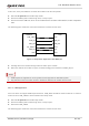


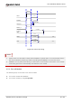
Table Of Contents
- Safety Information
- About the Document
- Contents
- Contents
- Table Index
- Figure Index
- 1 Introduction
- 2 Product Overview
- 3 Application Interfaces
- 3.1. General Description
- 3.2. Pin Assignment
- 3.3. Pin Description
- 3.4. Operating Modes
- 3.5. Power Saving
- 3.6. Power Supply
- 3.7. Turn on/Turn off/Reset
- 3.8. (U)SIM Interfaces
- 3.9. USB Interface
- 3.10. UART Interfaces
- 3.11. SPI Interface
- 3.12. I2C Interfaces
- 3.13. PCM Interface
- 3.14. Analog Audio Interfaces
- 3.15. LCD Interface
- 3.16. Matrix Keyboard Interface
- 3.17. SD Card Interface
- 3.18. WLAN Application Interface*
- 3.19. ADC Interfaces
- 3.20. Network Status Indication
- 3.21. STATUS
- 3.22. Behaviors of MAIN_RI
- 3.23. USB_BOOT Interface
- 4 Antenna Interfaces
- 5 Electrical Characteristics, Radio and Reliability
- 6 Mechanical Information
- 7 Storage, Manufacturing & Packaging
- 8 Appendix References

LTE Standard Module Series
EC200U_Series_Hardware_Design 35 / 94
V
IL
≤ 0.5 V
VBAT
PWRKEY
≥ 2 s
RESET_N
STATUS
(DO)
Inactive
ActiveUART
NOTE1
Inactive ActiveUSB
VDD_EXT
≥ 5.05 s
About 1.15 s
≥ 4 s
≥ 2.23 s
Figure 12: Power-up Timing
1. Please make sure that VBAT is stable before PWRKEY is pulled down. It is recommended that the
time interval between powering up VBAT and pulling down PWRKEY is no less than 30 ms.
2. PWRKEY can be pulled down directly to GND with a recommended 1 kΩ resistor if the module
needs being powered on automatically and shutdown is not needed.
3.7.2. Turn off Module
The following ways can be used to turn off the module:
⚫ Turn off the module with PWRKEY.
⚫ Turn off the module by using AT+QPOWD.
NOTE